Quantcast
Channel: Bentley Communities
Viewing all 289 articles
Browse latest View live

Upcoming AECOsim Building Designer Classes

$
0
0

Bentley has scheduled several AECOsim Building Designer Live Distance LEARN classes for the next days:

Sessions:

June 19thAECOsim Building Designer Architecture – Core Structure and Roof Modeling

June 19thAECOsim Building Designer Architecture – Floor Modeling

June 20thAECOsim Building Designer Architecture – Interior and Curtain Wall Modeling

June 25th - AECOsim Building Designer Architecture -Space Planner

June 26th - AECOsim Building Designer Architecture - Creating Design Documentation

June 27thAECOsim Building Designer Architecture – Schematic Design


If you are interested, you can find Detailed information about each class on the Bentley LEARN Server from the links above: (Login or Browse as Guest)


Tools -> Model Options -> Edit

$
0
0

 Welcome back to my blog and Happy Friday!  Today we will be talking about a dialog box that is used very often and for many reason in AutoPIPE... the Tools->Model Options->Edit dialog box. 

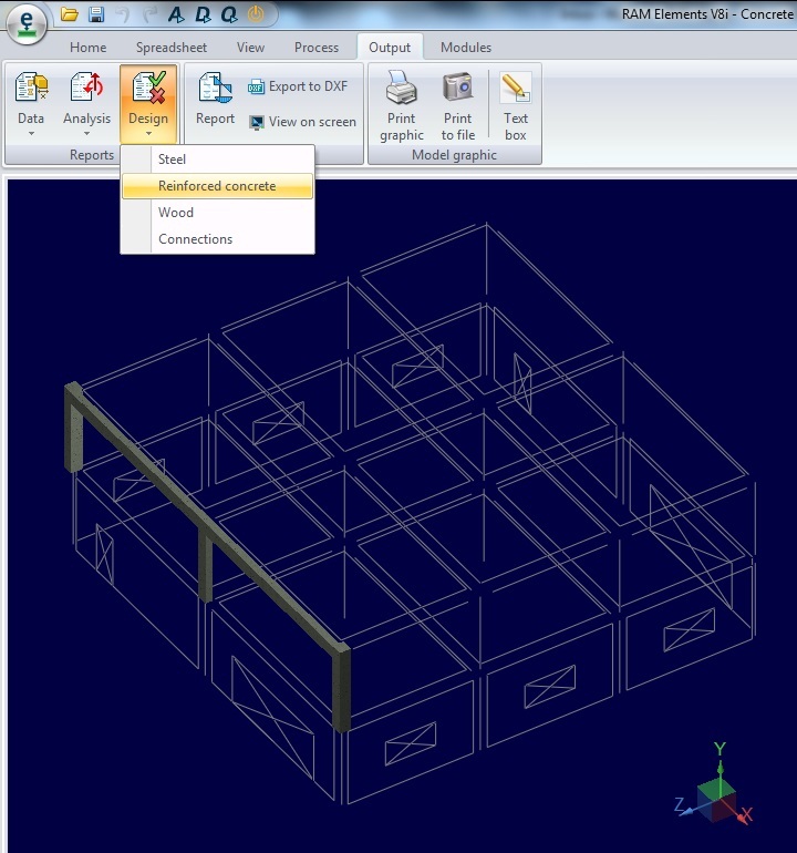
While in AutoPIPE, a user can access a dialog box that allows some basic controlling parameters to be changed from default settings based on user preferences, or according to company standards or project requirements.  To access this dialog box, click on the “Tools” tab on the main toolbar,
scroll down to “Model Options,” and then scroll over and down to choose “Edit”.


The defaults of this dialog box are active until the user manually changes them.  In order for the user preferences to be stored in the .dat file, the user must “Save” the file after changing the inputs of this dialog box.  The user can also change the default settings for all future models by clicking on  “Tools,” “Model Options,” then “Save Defaults” after changing the inputs of this dialog box.  


The “Digits after decimal for coordinates” box allows the user to assign the number of digits to show after the decimal point in many instances.  Then default value is two digits but the input can be changed to any number from zero to four.  This input affects the appearance of offset data in all dialog boxes and the output of coordinate and offset data in reports.  The change will also be seen on the Point Tab of the Input Grid, in the “Offsets,”  “Lengths and “Coordinates” columns.  When the “Show Length” button on the View Toolbar is turned on, the lengths shown in the modeling area will  show the change and when the “F3” is pressed and the Point Properties box appears for the active point, the Offsets and Distances will also show the change.  It is important for the user to be aware of the current units when inputting a number in this field.  Too many digits after the decimal can cause problems with larger numbers, because the number of significant digits for output fields is fixed, but too few digits may cause the program to round.


The “Default point name format” box allows the user to assign the node point names in the model to “Alphanumeric” or “Numeric.”  Alphanumeric format gives point names that include a letter and a number.  Since AutoPIPE uses segments in the modeling technique, Alphanumeric is the default format.  Each segment will have a different letter assigned to the point name.  The number part of the name will be incremented from point to point based on the user assigned preference in the next dialog box, “Default point name offset.”  If this value was set to “5,” for example, a segment in the model could have point names of A00, A05, A10, etc.  When the Numeric format option is chosen, the point names in the model will not include a letter.  Point names throughout the entire model will be numbered, also incrementing by the number assigned in the “Default point name offset” dialog box.  AutoPIPE will still use segments, but the user would only be able to tell them apart by looking at the Segment tab on the Input Grid.  When this dialog box is changed, the user will have the option to renumber the entire model or not.  If the user opts not to renumber the entire model, mixing between the two formats in a single model is acceptable.  If there are beams in the model, switching the format from alphanumeric to numeric and renumbering the entire model would skip the numbers that are already assigned to the beam point names when assigning point names to the pipe.


 The “Default point name offset” dialog box was previously discussed.  This value determines how the point names are incremented.  The default value for this box is one, which means that if the “Default point name format” was set to Numeric, the point names would be 1, 2, 3, etc.  If the “Default point name format” was set to Alphanumeric, the point names would be A00, A01, A02, etc.  When this dialog box is changed, the user will also have the option to renumber the entire model or not.

The “Replace all point names on renumber” is an input that can be toggled on or off when the “Default point name format” is set to Alphanumeric, but is always turned on when the “Default point name format” is set to Numeric.  When this option is enabled, renumbering a segment or the entire model will override any user specified point names.  User specified point names are any point names that lie on a segment but do no begin with the letter corresponding to that specific segment.


The “Use feet-inches display format” option can be enabled to show coordinate, offset and length data in dialog boxes, reports and input grid.  It will also change the display format when the “Show Length” button is clicked.  By default, this option is toggled off.  The box cannot be enabled if the input units under General Model Options are metric.


The “Mass points per span” dialog box allows the user to enter a value to in order to discretize the mass of the system to improve accuracy of dynamic analysis.  The assigned number will generate that many mass points spaced equally between existing nodes in the system to add mass points without actually having to insert runs to break up the model and capture the dynamic mass in the system.  The default value is zero, which will not add any mass points to the system.  “A,” meaning “Auto,”  could also be entered instead of a number, which generates the number of mass points
between two nodes automatically, based on the dynamic properties of each pipe span and the value entered in the “Cutoff frequency” field, which will be discussed later.  If anything other than zero is entered, the user should make sure to use this field consistently for static and dynamic analyses.  Although the model is broken up into mass points, there is no output report generated for those mass points.  The output report will still only include the node points assigned in the graphical model.  The mass points do not serve any function other than to provide better mass distribution to the system, because having to manually insert piping points would take too long.


If “Auto” is chosen for the “Mass points per span” dialog box, the user has the ability to assign a value to the “Cutoff frequency” box.  The value entered decides the frequency that the modal analysis will run until reaching.  Therefore, the assigned value will approximately match the frequency of the biggest mode shape, and will determine how many mass points are generated along the pipe between existing node points.  The user does not have the option to enter a value in this dialog box if KHK Seismic Level 2 is chosen as the piping code.


The “Use corroded thickness in all analyses” box can be enabled to use the corrosion allowance in the stiffness calculations for all analyses, such as longitudinal pressure stress and corroded section modulus used in bending stress calculations.  The pressure loads will still be used in the pressure analyses and all other calculations during the analysis will still use the nominal wall thickness.  If this box is disabled, which is the default, nominal wall thickness will be used for all calculations.  Like the “Cutoff frequency” box, the option to enable this box is not available when KHK Seismic
Level 2 is chosen as the piping code.


When a model is analyzed, warning messages pop up to warn the user about any issues.  When the “Suppress analysis warning prompts” box is enabled, warning boxes will not be shown for any non-fatal issues with the model.  Error messages, which show fatal issues with the model, will still be shown and will stop the analysis until the user accepts the message.  After the analysis is performed, a confirmation dialog will appear for the user to have the option to review all of the error messages.


In order to have the option to “Ignore flange effect on bend stiffness,” the user must use the Nuclear Version of AutoPIPE and select “ASME NB” as the piping code.  This option does not allow valves or flanges located at a bend point to affect the bend flexibility.  Enabling this box will not affect stress indices, but this box is disabled by default.


The “Distance L/D from flange/valve to bend” box determines how far upstream of a bend near point or downstream of a bend far point AutoPIPE will search for valves and flanges.  D is the nominal pipe diameter, or the outside diameter for nonstandard pipes.  Any flange within 3 points from the bend and less than the distance L will be counted but only one flange will be counted in each direction from the bend, even if there is more than one in that direction.  The default value for this box is 0.5.  Flanges or valves within this distance will increase the stiffness of the bend and reduce the flexibility and SIF factors.  Any flanges on the midpoint of a bend will be ignored by the program.  ASME B31.3 Appendix D explains the effects of flanges on bend flexibility in more detail.


The “Include Bourdon rotational effect” box can be enabled to include rotational effects at bends due to pressure in the pressure extension analysis cases.  The Bourdon effect explains the elongation and straightening that occurs at bends when pressure is applied.  The default is for this box to be disabled.  The option to enable this box is not available when KHK Seismic Level 2 is chosen as the piping code.

The “Pipe radius for Bourdon calculation” box allows the user to decide if the mean or inside radius of the pipe cross section is used in the Bourdon effect calculation.  The default is to use the mean radius, which is generally conservative.


Assigning a non-zero value to the “Coincident Node Tolerance” dialog box allows the program to perform a scan of the model to check for nodes that are close together, but not connected, and provide a warning to the user for possible further investigation.  The user may actually have wanted the nodes to be connected.  The program will include two nodes close together whether they are part of the same segment or not.  The default for this box is zero, which means that this check will not be performed.  AutoPIPE recommends a value of 0.04 ft. to be inputted in this dialog box.


The “Levels of undo” box defines how many times a user can undo or redo an action performed in AutoPIPE.  The default value is ten, but this user can assign any number, up to 98 undos.  After changing the value of this box, the amount of undos performed is cleared back to zero.


The “Rigid stiffness factor” dialog box allows the user to specify a stiffness factor to be applied to the material elastic modulus of any rigid components in the model.  The default value is 1000, but the assigned value must be between one and one million, and can be equal to one or one million.  The factor assigned here will be shown in the Analysis Summary output report.


The “Flange bolt/nut weight factor” dialog box is used to apply a weight to any bolts and nuts on flanges in the model.  The weight is calculated by multiplying this factor by the flange weight.  This weight is only applied to a flange if the “Use weight factor for bolt/nut weight” option is enabled in an individual flange dialog box.


The “Translation” and “Rotation” dialog boxes for “Support Rigid Stiffness” and “Anchor Rigid Stiffness” allows the user to define stiffnesses to be applied to any support or anchor defined as rigid.  The upper limit for these stiffnesses is 1E10 ft-lb/deg.


I hope this helped you understand the many options in this dialog box.  Have a wonderful weekend and I look forward to writing soon!


Thanks,

Jessica

Insider Skills - Heading into Week 2

$
0
0

Week 1 for ProStructures went well and considering this was the very first Insider Skills presentation, the attendance was very good.  We covered a couple of topics including:

  • How to bring your software together through ISM / ‘Structural Synchronizer’.
  • Bridging the ProStructures MicroStation and AutoCAD platforms.
  • A look at other forms of model exchange such as native element conversion; neutral file formats; NC files for plates and beamlines.

Each topic was covered and shown briefly so that a general idea of what they are and how they work could be presented and the feedback from this was positive. 

If you like, you can find a recording of the first Insider Skills session at the Bentley Structural page on YouTube or by clicking >>> here <<<.

We are now coming up on the second ProStructures presentation which will be covering a few quick tips and tricks about the Detail Center and Detail Style. Some of the topics may include:

  • Using descriptions for views and dimensioning
  • Using the ‘Cut’ option to show hatching
  • Using the ‘Anchor’ option for views
  • Saving templates for the ‘detail center’ filtering.
  • Modifying the ‘US Mark Number’ (.mkn) file. 

With this in mind I hope you will join us again next Friday, July 5th at 1 PM Eastern / 12 Noon Central / 11 AM Mountain / 10 AM Pacific by clicking here to join at the specified time.

Announcement: ProStructures Online Training Schedule

$
0
0

We are about to post the ProStructures classes for the second half of 2013.

On the Learn server you will be able to register to:

ProSteel for MicroStation:

Fundamentals (3, 4 or 5 days):

    • Modeling (from Monday to Wednesday)
    • Engineering General Arrangements (Thursday) - Mandatory to be registered to Modeling class (or to have followed Modeling class at an earlier date)
    • Fabrication Shop Drawings (Friday) - Mandatory to be registered to Modeling & General Arrangement classes (or to have followed Modeling & General Arrangement classes at an earlier date)

For Advanced Users (3 days - Tuesday to Thursday)


ProSteel for AutoCAD:

Fundamentals (3, 4 or 5 days):

    • Modeling (from Monday to Wednesday)
    • Engineering General Arrangements (Thursday) - Mandatory to be registered to Modeling class (or to have followed Modeling class at an earlier date)
    • Fabrication Shop Drawings (Friday) - Mandatory to be registered to Modeling & General Arrangement classes (or to have followed Modeling & General Arrangement classes at an earlier date)

For Advanced Users (3 days - Tuesday to Thursday) – Prerequisite to have ProSteel modeling knowledge. Enginnering and Fabrication classes a plus.


ProConcrete for MicroStation:

Fundamentals (2 days – Tuesday & Wednesday)Prerequisite to have ProSteel modeling knowledge. Enginnering and Fabrication classes a plus.


The classes are not posted yet but will be very shortly on our Learn Server. They will be available as follows (all classes go from 8am to 5pm, Eastern Times - North America):


August:

  • 05 to 09 : ProSteel Fundamentals for MicroStation*
  • 13 & 14 : ProConcrete Fundamentals for MicroStation*
  • 19 to 23 : ProSteel Fundamentals for AutoCAD

September:

  • 10 to 12 : ProSteel Advanced for MicroStation*
  • 17 & 18 : ProConcrete Fundamentals for MicroStation
  • 24 to 26 : ProSteel Advanced for AutoCAD*

October:

  • 07 to 11 : ProSteel Fundamentals for AutoCAD
  • 15 & 16 : ProConcrete Fundamentals for MicroStation

November:

  • 04 to 08 : ProSteel Fundamentals for MicroStation*
  • 12 & 13 : ProConcrete Fundamentals for MicroStation*
  • 25 to 27 : ProSteel Advanced for AutoCAD* (because of American Thanksgiving days have been moved from Monday to Wednesday)

December:

  • 09 to 13 : ProSteel Fundamentals for AutoCAD
  • 17 to 19 : ProSteel Advanced for MicroStation*


* : classes that I should be delivering

Tip No.6: T.O.S. Elevation difference for elements in plan views

$
0
0

When generating general layouts, one can have ProSteel automatically give us the elevation difference between the default elevation of the plan view and any elements that are above or below it. Here we will look at the settings needed for this to work.

It is important to understand that the calculation is made in reference to the elevation of the workframe view (magenta rectangle) used for that particular plan view.

All the controls in order to do this are in the DetailStyle.

We will look at the plan view of this little structure, which has a few internal beams above TOS, some below and some at same TOS as Workframe.

The result will be a plan view like this:

Where only elements with TOS above or below TOS of plan view show their difference value (inside brackets) in reference to TOS of view.

The way this was achieved was using a code inside the DetailStyle. In this case we used the $(N) for the name of the elements, followed by an “exception” rule, meaning that if the code inside this rule is empty (or equal to zero), the whole code inside this rule will be ignored. This makes it so that elements at “good” TOS elevation will not get a 0 (zero) value inside brackets. The exception rule  is the $(X, ????) where the ???? are replaced by whatever code you want to use. In this case we used the $(E) (which is the elevation of the element) inside brackets giving us a final code of:

$(N)$(X, [$(E)])

We could’ve used the following code $(N) $(X, [EL=$(E)]) to get a result like this W200x19.3 [EL=-40]

Now that the code is entered in the text format field, we also need to tell ProSteel to apply it to the elements we want to apply it (we do not want this for the columns in this view).

This is done by going back to the “Object display” page under  “2D Display > Views” and setting the Part name to be using the “Global Format String”


Did You Know? RAM Connection Shear Connections

$
0
0

Did You Know… RAM Connection has an extensive library of connection types built into the program? I frequently am asked, "Can RAM Connection do [     ]?" where the blank is filled in by a specific connection type.

This will be the first of two blogs providing an overview of connection types in RAM Connection. In today’s blog, I will cover shear connections. Moment connections and combined connections will be addressed in the next blog.

Most connection types in RAM Connection are available two ways:  Basic or Smart.  In the instance where a connection is only available as one type, I have noted it.  Otherwise, the connection is available as both types.

For a quick reference guide of connection types and their descriptions, download the attached PDF.

The following is a list of the majority of the shear connections available in RAM Connection.  This list was compiled for beam to column connections except where noted as a splice connection.  This is not an exhaustive list.  RAM Connection is customizable and it would be difficult to itemize every single connection available.

Shear Connections

1. Shear Plate

2. Through Plate (HSS) [Basic only]

3. End Plate Bolted

4. End Plate Welded

5. Double Angle All bolted

6. Double Angle All welded

7. Double Angle Welded to Support, Bolted to Beam

8. Double Angle Bolted to Support, Welded to Beam

9. Bent Plate Bolted (can also be welded) [Basic only]

10. Shear Tee All Bolted

11. Shear Tee All Welded

12. Shear Tee Bolted to Support, Welded to Beam

13. Shear Tee Welded to Support, Bolted to Beam

14. Stiffened Seated Angles

15. Stiffened Seated Plate

16. Stiffened Seated Tee Bolted [Smart only]

17. Stiffened Seated Tee Welded [Smart only]

18. Unstiffened Seated Bolted

19. Unstiffened Seated Welded

20. Column Splice Flange Plate Bolted [Basic only]

21. Column Splice Flange Plate Welded [Basic only]

22. Column Splice Shear Plate [Basic only]

23. Beam Splice Shear Plate

24. Beam Splice Double Angle [Smart only]


Insider Skills - Session 02

$
0
0


Even with the July 4th holiday in the USA yesterday, attendeance was good. A wonderful group of people turned out to check out some of the information provided in the latest Insider Skills session. This weeks session focused on 2D Detail Center related items and covered things like using the 'Anchor Point' & the use of 'Descriptions' in the 2D drawings as well as a few other topics. As a matter of fact, though three and sometimes four topics are presented, this was an unprecedented five topics which meant that each topic needed to be covered quickly in order to finish on time. The presentation went well however and many satisfied attendees responded with positive feedback. So thank-you all, you should know that your feedback is always appreciated, whether it is positive or otherwise.

For anyone who did not get to attend this session a new session for ProStructures is held on the first Friday of each month at 1PM Eastern. More information can be found here:  >>> Click Here <<<  Additionally if you are interested in AutoPIPE, RAM or STAAD.Pro, the same link provides information on how you can attend the Insider Skills sessions that apply to each of these.

 Let me end by saying, I hope to see you all at the next session and if anyone missed the first 'Insider Skills' session you can find it online here: >>> Click Here <<<

EDIT: July 10, 2013

The second session has just been posted and can be found here:>>> Click Here <<<


Critical Issues in CONSPAN v12.01.00.57

$
0
0

Critical Issues in CONSPAN v12.01.00.57

A couple of critical design issues have recently been identified in CONSPAN v12.00.01.57. Users should review these two issues carefully and verify the impact on prestress girder designs. These issues are being fixed, and the fixes will be included in a new release which will be available on SELECT at the end of July. If you have any questions or need additional information regarding these issues, please contact technical support at 1-800-778-4277, option 6 then 7 for LEAP.


  1. Vertical Shear: When the option to use Simplified Shear procedure (LRFD article 5.8.3.4.3) is used, the design shear Vu was incorrectly using the shear corresponding to the maximum moment
    rather than the maximum shear. Since this could lead to potentially underestimating the shear reinforcement required, users should not use this option, and should use the other options available under Design Parameters / Moment and Shear Provisions tab, i.e. the Beta Theta Tables or the Beta Theta Equations method.
  2. Live load distribution factor for multi-stemmed beams: When using Lever Rule the distribution factors were computed incorrectly by considering the distance from the edge of curb to the center of exterior web rather than to the center of the beam. This issue only affected exterior beams, and could be critical if the exterior beam governed the design.


Did You Know? RAM Connection Moment Connections

$
0
0

Did You Know… RAM Connection has an extensive library of connection types built into the program? I frequently am asked, "Can RAM Connection do [ ]?" where the blank is filled in by a specific connection type.

This is the second of two blogs providing an overview of connection types in RAM Connection. In today’s blog, I will cover moment connections and combined connections. Shear connections were addressed in my previous blog.

Most connection types in RAM Connection are available two ways: Basic or Smart. In the instance where a connection is only available as one type, I have noted it. Otherwise, the connection is available as both types.

For a quick reference guide of connection types and their descriptions, download the attached PDF.

The following is a list of the majority of the moment and combined connections available in RAM Connection. This list was compiled for beam to column connections except where noted as a splice or cap connection. This is not an exhaustive list. RAM Connection is customizable and it would be difficult to itemize every single connection available.

Moment Connections 

1. Flange Plate Bolted

2. Flange Plate Welded

3. Moment Angle Bolted

4. Directly Welded [Smart only]

5. Cap Plate

6. Beam Splice Flange Plate Bolted [Basic only]

7. Beam Splice Flange Plate Welded

Combined Moment and Shear Connections

8. Beam Splice Flange Plate Shear Plate Bolted [Basic only]

9. Column Splice Flange Plate Shear Plate Bolted

10. Moment End Plate Extended Both Ways

11. Moment End Plate Flush

12. Moment End Plate Extended One Way (up or down)

13. Beam Splice with Moment End Plate Flush

14. Beam Splice with Moment End Plate Extended One Way (up or down)

15. Beam Splice with Moment End Plate at Apex

16. Beam Splice with Moment End Plate at Apex Extended Upwards

17. Moment End Plate Knee Vertical

18. Moment End Plate Knee Horizontal

19. Moment End Plate Knee Perpendicular

20. Moment End Plate HSS [Smart only]


Offsets in RAM Structural System

$
0
0

One of the newest features in RSS is Offsets and Rigid Links.  This feature has been in RSS since last year but is not being widely used.  Hopefully the Inside OUT of Offsets will give you the confidence to jump in and use them in your analysis.  (Based on RSS v14.05.03)

Probably more widely thought of  in concrete construction the Offsets command works for  Beams and Columns of material type Steel, Concrete, and Other.  It is also available for Beams designated as Smart Beams.  (Offsets are not available for Steel Joists or Walls.)

Offset Command - How it works

With your framing drawn in a traditional manner- columns on grid lines with beams framing between- specify a distance to move the beam or column and then select the member. 


Offset Command - Behind the scenes

Your member was moved in plan and RSS assigned a rigid link connecting the end of the beam with the center of the column. 


What is a Rigid Link?

Whether you Google the term or have learned it in a structural analysis course, a Rigid Link is a infinitely stiff element that connects two nodes.  Curiously enough this term is common in FEA analysis and in General FEA programs.  RSS uses a rigid link in the same way a general analysis FEA software (RE, STAAD, competitors) would. 

The Rigid Link connects two nodes that are non-coincident.  Preventing unsupported beam errors and free standing column errors (under one-way deck).  Allowing load transfer between elements and calculation of additional moments due to the eccentricity from the center of the members.


Free Form Offset Modeling - How it works

If you prefer to draw the structure in the actual location, ie starting out with unsupported beams, offsets are still possible by manually assigning the rigid links.

With the framing already drawn, select the rigid link command.  Select the end of the beam (or center of the column) and then select the center of the supporting column.


How does this affect my analysis?

In the years before the offset command, as engineers we rationalized the resulting moments from any offsets are small enough to be insignificant.  Depending on geometry these extra moments can be large.  Using the offset command will ensure you capture these additional forces.


Are there any integration advantages to using Offsets in RSS?

Offsets are fully supported in ISM and are maintained in Revit and AECOsim.  This allows accurate representation of the model in both the BIM  realm and the Analysis realm.


Watch Offsets in action as I assign, analyze, review, and integrate.

(Please visit the site to view this media)


Idiosyncrasies

As with any new tool there are some quirks that we need to get used to. 

  • If the edge of slab was defined as an offset from the member it will move with the member Offset.
  • If you want to change or remove the offset it's easier to delete the member and re-frame.
  • Offsets/Rigid links are assigned to the top of the column on plan only.


Don't let projects get you overstressed, RAM gives you strength. 


amgh

Useful View Toolbar Commands

$
0
0

Hello everyone!

Today I am writing about some useful features on the View toolbar that many people do not know about.  Or maybe you know these options are available but you don't ever use them.  When AutoPIPE is opened, the View Toolbar is located on the left side of the screen.  It is a floating toolbar, so the user can choose to move it from the left side of the screen and place it anywhere within the modeling area, by simply grabbing the top of the toolbar. 

This toolbar includes buttons for the most common view tools, such as zoom, pan, rotate and common view angles.  It also has some other very useful tools that are worth learning about.

Display Mode

There are three Display Mode buttons.  These buttons determine if the model is being represented as a Single Line, Wire-Frame or Solid Model.  The default setting is Single Line mode, but users may work in any mode and have the ability to switch between modes for best results.  The mode that is currently active will be indicated by the button looking like it is "pushed in" on the View Toolbar.


                                                    Single Line


                                                        Wire-Frame

                                                  Solid Model

The user has the option to change the number of wires represented when the Wire-Frame mode is chosen.  This option can be found under View --> Settings.  The user can change the number of wires to any number from 4 to 20 under "No. of Wires."


Viewports

There are also three viewports that the user can choose to view the model in.  The viewport buttons determine whether the modeling area is split up into one, two or four viewports based on the Single Viewport, Double Viewport and Quad Viewport options.  The viewport mode that is currently active will be indicated by the button looking like it is "pushed in" on the View Toolbar.  The different viewport options help the user to easily work in a view which is convenient and can be switched back and forth while modeling and/or viewing results.  To modify or use the View Toolbar common tools in a specific viewport, make sure to click on the viewport first so that it appears highlighted with a yellow box around it.


                                                     Single Viewport    


                                                   Double Viewport

                                                    Quad Viewport

Show Options

There are a lot of different Show Options directly on the View Toolbar.  These options include Show Pipe Properties, Temperature, Pressure, Additional Weights, Concentrated Forces, Imposed Displacements, Thermal Anchor Movements, Valve Data, Flange Data, Tee Data, Soil Properties, Length, Reference Points and Joint Type and User SIF Data.  The Show Pipe Properties button brings up a dialog box to choose between graphically viewing the model by Pipe Daimeter, Schedule, Wall Thickness, Pipe Material, Pipe Identifier, etc,  The View Toolbar also includes a Show Reset button that can be used to reset all of the options selected to the default settings.  While going to View --> Show Options allows the user to access even more show options, it is helpful to know that these common option buttons are available with one simple click.  Hover over the buttons in the area of the Show Options on the View Toolbar to understand what each button shows in the model.


                                                   Show Temperature                                              


                                   Show Valve, Flange & Tee Data      


                                                          Show Length    

The Show Options button on the bottom right of the View Toolbar opens up the Show Options Dialog box, which can also be accessed by View --> Show Options...  This dialog box provides all of the different options to plot data and components in the model.  The user can choose to plot Pipe, Structure and Support Properties, Component Data, Xtra Data and Color Plots and also Show Connected Segments here.  The user can also Preview the updates to the model plot before accepting the changes.  This is a very useful dialog box, take the time to look at it and understand the options.


Measure Distance

The Measure Distance button acts as a graphical distance calculator.  It can be used to check distances and clearances between pipes and structures.  The user would select the Measure Distance button and then choose the FROM and TO points and click Calculate down on the Status Bar.  Remember that the Status arBar is in the lower left corner of the screen.  The user can choose the FROM and TO Points by clicking on points in the model with the mouse or typing in the name of the points.  The DX, DY and DZ Offsets and the straight-line distance will then be displayed in the Status Bar.  To stop using the Measure Distance tool, simply click Close  on the Status Bar.


Show Insulation

The Show Insulation button can be used to display the insulation on any piping in the model in a transparent color.  It does not give specific properties about the insulation, but simply shows which piping has insulation.  The color of the pipe insulation can be changed by going to Tools --> Settings --> Colors and choosing PipeInsulation.


I hope this information about the View Toolbar was useful to you!  There are many easily accessible options on the toolbars in AutoPIPE that are often overlooked or forgotten about.  Try to get used to using these tools, as the simple one-click button method will make your modeling and viewing results more efficient!

Thanks!

SS5 - DWT Creation (Best Practices)

$
0
0

PS V8i (SS5) – DWT Creation - Best Practices for AutoCAD

  Chapter One  

Before beginning to generate a model in ProStructures, many of the underlying settings should be in place. There are quite a few settings to consider but fortunately, most of these can be saved to a Drawing Template (DWT) and loaded each time a new model is to be created. It is the understanding throughout this post that you already know how to create and save an AutoCAD .DWT file.

Throughout this document we will look at some of the more relevant features and settings that can be added to the DWT. This is not meant as a feature by feature guide to all the settings available, nor is it meant as an absolute requirement to generating your models and drawings. What we will be looking at is settings that represent key features in generating good models.

Additionally this document has been divided into two areas due to the fact that the DWT used for generating 3D models and the one used for generating 2D drawings should be set up differently.

Now let’s begin by looking at some of the settings for the 3D modeling environment.

  Section 1.1 – 3D – The Global Options  


The ‘Global Options’ have many settings that handle all kinds of functions throughout the ProStructures program. It is not my intent here to cover each and every setting but simply to point out some of the key settings that you may wish to take note of.

First of all let’s look at how we access the Global Options. With ProStructures loaded there are two ways to open up the Global Options dialog window, first you can go from the dropdown menu that is available in AutoCAD (Though not always enabled) by going to “ProStructures à ProSteel Options”.

The second method is to have nothing selected and right click in the model space area and from the menu that appears select “ProSteel à Options”.

 Both methods will open up the Global Options dialog window. From this dialog we have access to many of the global features available in ProStructures and we will be focusing on a couple of key features for this document.

-=-=-=-=-=-=-


First let’s begin with the ‘Options’ area.

The first settings we should look at are the “Remove” settings. Note that there are three settings that begin with the word remove. Each of these settings attaches to the purge command when enabled and allows the user to purge out not only the standard
AutoCAD entities but also the ProStructures specific entities.

Immediately following these options is the Check DWG during load. This is an important setting as it will check the drawing for errors whenever it is loaded. For this function properly however the “Proxygraphics” must be disabled (Set to ‘0’).
Proxy graphics is an AutoCAD command so you can simply type this into the command line to change the setting. Another bonus to having the Proxygraphics disabled (Set to ‘0’) is that the file sizes can be up to ten times smaller.
This also gets saved with the DWT (Drawing Template).

Lastly, turn on the ‘Convert Boolean’ and ‘Execute Boolean First’. The simple explanation for this is that it will allow you to open and manipulate much larger files if these settings are enabled.

-=-=-=-=-=-=-

The next setting I’d like to mention is the “Length always largest value” setting under the ‘Straight Plates --> Plate Description’ area. Please ensure that this option is not enabled as, depending on how a plate is drawn, it may cause the values of your BOM to be displayed incorrectly.

Leave this setting ‘Unchecked’.

-=-=-=-=-=-=-

Another important setting is the Actual Geometry’ setting found in the ‘Straight Plates --> Calculation Method’ area.

The ‘Calculation Method’ setting from the dropdown box will affect the weights listed in you BOMs. For actual weights set this to ‘Actual Geometry’. If you are doing fabrication and want to include the weight of the wasted material you may want
to change this to ‘Extents’.

-=-=-=-=-=-=-

In the Bolts Section You may want to ensure that the “Enable Back to Back Bolting” is enabled.


If you are connecting beams using clip angles as an example and these beams go to either side of a supporting members web then this will recognize that the holes line up and handle the bolts used in this situation correctly.

-=-=-=-=-=-=-

 In the ‘Values’ section of the ‘Global Options’ you will find two settings, one for ‘Front Distance’ and the other for ‘Back Distance’.

These settings will control your default clipping plane distances which in turn will also affect all of your viewtools that cause clipping planes to be enabled.

-=-=-=-=-=-=-

Passive and Active Logical Links should be enabled (Checked).
These settings allow your model to dynamically react to changes once things like coping or connections have been put into place. Set the Update dropdown boxes to Automatically.

You may also wish to enable the ‘Allow Additional Data’ option if you intend to call out Connection details. This will enable and additional tab when connections are being placed that allows the user to add in a description and identifier. If
these fields have values then you will be able to call the connection in as a detail during the 2D drawing production phase.

-=-=-=-=-=-=- 

Three important settings in the 'Display Area'.

First the paperspace viewport options should be set to ‘Without Support’ while modeling and only enabled once the model is done and the 2D drawing generation begins.

Also you may wish to ensure that the ‘Shape and Plate Clipping’ options are enabled. This will allow the program to display the cross section of shapes when looked at from the center area where the clipping depth does not reach the end of the member.

Lastly ‘Do not display Part Labels’ should be disabled (Unchecked) or else all labels everywhere will be hidden regardless of any other setting.

-=-=-=-=-=-=- 

The settings for the 'Dialog settings' area are usually set as follows:

“Use CAD System settings” in all three instances as enabled (Checked). This then retrieves the values used from AutoCAD that were set up when ‘UNITS’ is typed at the command line. Units should always be set regardless and here the user has the ability
to call those settings in.

“Expert Mode” is typically set to “Beginner”. Changing this setting, especially to Expert mode may provide additional settings in different areas but the user then loses the ability to use the graphical reference at the right side of the dialog windows while working.  If the extra features are needed it is recommended that the user come into the Global Options, switch to ‘Expert’ mode to use these features and when done change back to ‘Beginner’ mode. For the sake of the DWT, leave this setting to ‘Beginner’.

-=-=-=-=-=-=-

 At this point you may wish to generate a template for your settings so that if they are ever lost for whatever reason calling them back will be easy with the template in place.

Again, please note that this is not an exhaustive list of features and settings but rather some of the highlighted ones that may prove useful. A good suggestion is to start with the provided drawing templates that come with ProStructures. For North America this is typically the “PS-S#-US-CDN_Imp” or “PS-S#-US-CDN_Met” as these drawing templates have many of the best settings already in place.

  Section 1.2 – 3D – Additional Items to Consider  

In addition to the settings mentioned in the first part you may also want to consider setting up and including the following items. 

  • ‘Proxygraphics’ should be off (Set to ‘0’). You can type this command at the command line.
  • ‘Units’ should be set properly. You can type this command at the command line.
  • Your AutoCAD dimension styles
  • Your AutoCAD text styles
  • Display and Area Classes from within ProStructures (Optional)
  • Part Families from within ProStructures (Optional)
  • Global Options (above) set properly.


  Chapter Two  

  Section 2.1 – 2D – Drawing Template for 2D Detailing  

When it comes to developing a ‘Drawing Template’ for 2D drawing creation, this should be a separate file from the 3D drawing template. In the case of setting up a 2D environment you do not want to include anything except what is absolutely necessary. For example, you may have a border/’title block’ included in the file but then only the text styles used with this border should be included and nothing else. 

The reason for using a clean file for the 2D drawing is that when 2D drawings are generated through ProStructures, all of the necessary files are brought over from the models environment. To avoid conflicts or errors it is best to leave the 2D drawing template as empty as possible so that it is ready to receive everything from the models environment.

 As stated in the training manual for this product, “ For 2D drawing generation, ProStructures takes all required text and dimension styles specified in the Detailstyle from the model and brings them over to the 2D drawing.”


   Chapter Three  

  Section 3.1 – Additional Information  

The document can be found online here:

http://communities.bentley.com/products/structural/drafting___detailing/m/drafting_and_detailing_gallery/249464.aspx

News: First ProConcrete training has been delivered

$
0
0

I want to share with you my experience with delivering our first ProConcrete onsite training. It was delivered last week in Hopkins, MN (Suburb of Minneapolis/St. Paul).

The standard ProConcrete training is 2½ days (20 hours). It could be 2 days (16 hours) if the people being trained already have ProSteel experience since some tools are common to ProSteel & ProConcrete. In this case it was a new user that had never used either software.

We had scheduled 4½ days at the client's offices using 2½ days for training and 2 days for coaching.

The training went fine from Monday to Wednesday a little after mid-day. The client has some very specific type of structures they build and needed a more personal approach on how to model the structures they normally build. Because of this, we took a bit of time out of the coaching part to accommodate the training.

The coaching part was intended so that the users could use their knowledge during training to build something that resembles more of what they really do and have the instructor around to help and answer any questions. The reason for this is that the training was to be delivered using the exercises prepared in our manual which did not necessarily reflect what the client produces in real life. The manual is intended to show how to use the commands in a general way so the users have the knowledge of what the software can do, not necessarily showing what they do in a day to day basis.

Since this was the 1st training delivered for ProConcrete in North America, using a new manual and dataset, some comments and propositions from the users that attended this training will be looked at in order to make the training material better.

The general feedback from the users present was positive. There is a return trip to be schedule with this client in order to pursue the coaching and possibly revise some of the topics covered in the training later this fall.


On another note, I'd like to thank the Air Canada crew for their superb job handling the uncontrollable circumstances that occurred during my return trip on Friday after the class was over. As you might have heard, there was a major thunder storm in the North East area which closed my connecting airport (Toronto's Pearson International, a.k.a YYZ) for a few hours and also closed my home town airport (Montreal's Pierre-Elliot-Trudeau International, a.k.a YUL).

My trip started a 1:00pm at Minneapolis-Saint Paul International (a.k.a. MSP), once in the air, about 45mins before scheduled time to arrival at YYZ, the captain came on air to announce that YYZ was shut down, we were to be redirected to North Bay (not an international airport...meaning no customs). So we landed there, and because there is no customs at that airport, we had to stay on the tarmac, inside the plane, for 4 hours, until Pearson re-opened. During this time we had no food, and no more water bottles were available on the plane since this flight was schedule to be only 2¼ hours long.

The captain was about to take it upon himself to allow us to de-board the plane (this is a procedure normally used in private planes, but can be applied in special circumstances) when the air traffic controller came on to let us know we were cleared to take off and head back to YYZ. We landed there at 10:45pm

Needless to say, by the time we reached YYZ, my connecting flight to YUL should have been gone. Well no it wasn't. It was also delayed because of the closure of both airports I had to fly to (YYZ & YUL). This flight was supposed to leave YYZ at 8:30pm, but was delayed and only departed at midnight. Giving me time to clear customs and find my gate.

I finally arrived home 13 hours after I arrived to MSP airport. But the trip was pleasant thanks to a superb crew who did all they could to make us comfortable.

Did You Know? RAM Elements for Concrete Design & Detailing

$
0
0

When using RAM Elements for concrete structures, did you know that there are multiple ways to have the program perform design and detailing functions?  Method #1 uses design options from directly within your 2D/3D model.  Method #2 uses design and detailing options located in the Modules.

Let’s take a look at a sample concrete structure and review the design and detailing options available.

Our model is a two story structure with lateral concrete frames at the upper story and concrete shear walls at the lower story.  The walls have integrated concrete pilasters that continue down from the columns above.  I’ve modeled a two-way concrete slab to distribute the surface dead and live loads.  For lateral loads, I’ve modeled equivalent wind point loads in the X direction as well as pressure component loads on the walls in the X direction.  For scale, the bays are 20 ft x 30 ft, and the stories are 12’-6” floor to floor.  The model has been analyzed and designed.


Method #1 – Slab, Wall, Beam, and Column Design within the 2D / 3D model


Slabs / Walls:  Select the View tab and the Stresses button.  For a concrete shell element, you may select AS1 or AS3 from the drop down menu to see a color-coded output of required area of flexural reinforcement in each of the principal directions, both top and bottom.  This will NOT choose the bars, only provide an area of steel.  Be sure to set your mechanical cover in your shells dialogue for correct output.


Beams / Columns:   Select the beams and columns for which you wish to obtain design results.  Then go to Output -> Design -> Reinforced Concrete.  Make your selections in the dialog box and click OK.  You will get a design report for each member’s required area of longitudinal steel and tie size and spacing.  This will NOT choose the bars, only provide an area of steel.For beams, axial forces and weak axis shear and moments are not considered.  For columns, torsion is ignored.


Method #2 –Wall, Beam, and Column Design within the Modules


Walls:  In the 3D model, select walls and columns in a single plane.  From the Modules tab, select the drop down menu to Asssign -> Concrete Wall.  The entire wall element with pilasters will be imported into the Concrete Wall Design Module.  Make your design selections for allowable bar sizes and spacing, and click Optimize.  The program will choose bar layout for the walls and columns, which may be viewed on the Detailing tab.


Beams:  In the 3D model, select beams in a horizontal line.  From the Modules tab, select the drop down menu for Beams -> Concrete.  The entire beam line, including support information, will be imported into the Concrete Beam Design Module.  Make your design selections for allowable bar sizes and spacing, and click Optimize.  The program will choose bar layout for the beams, which may be viewed on the Detailing tab.


Columns:  In the 3D model, select columns in a single vertical line.  From the Modules tab, select the Concrete Columns button.  The entire column line, including supported beam information, will be imported into the Concrete Column Design Module.  Make your design selections for allowable bar sizes and spacing, and click Optimize.  The program will choose bar layout for the columns, which may be viewed on the Detailing tab.


Now that you know about RAM Elements’ concrete design and detailing options, be sure to put them to use with your next concrete structure!


NEWS: SS6 Release and AutoCAD 2014 Support

$
0
0


In case you haven't heard, here are a couple of things that have been announced lately.

  • The SS6 version of ProStructures will soon be released. 
  • AutoCAD 2014 support is now available.
  • Information about the Migration Assitant, the Archiving Assistant and Enhanced Section and Material Mapping for ISM is now available.
  • There is a new standard stair utility being released.


You can find more information about these here:

http://communities.bentley.com/products/structural/drafting___detailing/w/structural_drafting_and_detailing__wiki/7116.aspx


To create a Saved View from New or Existing Callouts within a Sheet Model

$
0
0

Imagine a scenario where you are working on the front view of a 3D model for a house. You are required to produce a top-view of the foundation for this 3D model. Using the Detailing Symbols tools a callout can be placed along the line of the foundation in the front view that generates the desired dynamic view. The position of the callout can be modified to dynamically change the position of this view.  Once this dynamic view has been generated you may find it of interest to learn about the origins of their attributes.

A series of blogs has been produced that will aid you in the construction of dynamic views using common scenarios. These should provide you with an insight as to where the Saved View attributes have been inherited.

Follow these steps to create a new dynamic view on a sheet model:

  1. Open an existing design file containing a 3D design model.
  2. Go to Tools > Detailing Symbols > Place Section Callout.
  3. Select Drawing Seed. (see Drawing Seed blog)
  4. Select the Create Drawing check-box.
  5. Select the start, end and depth to place the Callout. The “Create Drawing” dialog will open.
  6. Select the “Create Drawing Model” and “Create Sheet Model” checkboxes to create a drawing and sheet model.
  7. Click OK. A new saved view and its drawing and sheet models will have been created.

Roof and Floor loading without the Roof or the Floor

$
0
0


 Roof and Floor loading without the Roof or the Floor  

In STAAD.Pro, 
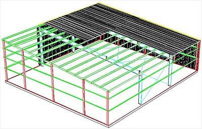
there are many ways to properly account for loading to be distributed across the structural framing of roof and floor members. We will discuss some of the practical options for accurately assigning uniform pressure loads to roof and
floor members without modeling the slab or deck that distributes the loading to the structural members.


For this discussion we will focus on vertical loads due to gravity for Dead Load, Live Load, and Snow Load. There are a few considerations that we want to think about
before we begin the process of creating our roof and floor loads. The following are a few questions we can pose to help decide which STAAD.Pro loading tools which best suit the structural framing:


Do we have openings in sections of the floor or roof? Are portions of the framing system sloped? How is the uniform loading on the framing changing within each load case and also between separate load cases? What is the complexity of the structural member layout? Is the layout a simple rectangular bay system or are there curved members and variable member spacing?

The reason these questions are important for applying loading to the model is that the answers to these questions will help determine the most useful tools within STAAD.Pro to address the calculation, application, and automation of load distribution to our structural framing. Tools like floor beam groups and configurable floor loading make it possible to quickly calculate, apply, and adjust distributed loading to floor and roof systems.

Using floor beam groups will allow us to assign distributed loads to a set group of members without having to apply the load to the entire floor system. This tool works well in cases where loading varies across different portions of the floor or in a situation where the framing is sloped.


STAAD will automatically calculate the tributary area for the floor or roof member group
and apply the calculated uniform load as a one way or two load distribution based on your selection. Using the floor load command, you are able to apply a pressure load such as dead load due to a slab, or an assumed live load for roofs and floors, or a snow load to a group of members on a designated area of
the structural framing. For example this method works well for dead load due to
a slab, where the slab thickness and weight will be the same on multiple floors
however the framing layout or spacing will vary from floor to floor. Rather than manually calculating the tributary area for each member and assigning a uniform load on members one by one, the floor load can be designated to several floors at once and the uniform load for each member will be calculated automatically by STAAD.Pro based on the member tributary area.


It is necessary to fore warn you that not all floor configurations will allow STAAD.pro to automatically calculate the uniform load based on the member tributary area. Therefore, in complex structural framing situations it may be necessary to use multiple floor member groups or possibly even manually assign the uniform loads to members in order to accurately generate loads on the structure.


For single sloped roofs one floor group may be all that is required to assign the pressure loads to the structural framing. However for gable or hip roofs one floor member group will be required for each portion of the roof with an individual slope.


For additional information on floor loading in STAAD.Pro refer to the technical reference manual pages 5.32.4.3 Floor Load Specification. I hope that this information has been useful. Please feel free to email me with additional questions.

Thanks

Karimu.Rashad@Bentley.com

News: Insider Skills eSeminars

$
0
0

The 3rd Insider Skills FREE eSeminar for ProStructures has been delivered.

This was the 1st of these ProStructures eSeminars talking about ProConcrete. The topics covered were the placement of concrete & reinforcement.

If you missed the eSeminar (or want to see a past eSeminar), you can find them all (ProStructures, AutoPIPE, STAAD, RAM) on our YouTube channel here.

Here is a list of all the Insider Skills delivered up to date with link to their recording. 

#ProductDateTopicLinks to videos
1ProStructures June 7th 2013IntegrationPart 1 / Part 2
1AutoPIPEJune 14th 2013IntegrationPart 1
1STAADJune 21st 2013IntegrationPart 1
1RAMJune 28th 2013IntegrationPart 1
2ProStructuresJuly 5th 2013DetailCenterPart 1
2AutoPIPEJuly 12th 2013Top FeaturesPart 1
2STAADJuly 19th 2013Top TipsPart 1Part 2 / Part 3
2RAMJuly 26th 2013Efficiency TipsPart 1 / Part 2 / Part 3Part 4
 3ProStructuresAugust 2nd 2013Concrete & RebarPart 1 / Part 2 / Part 3


Here are the remaining eSeminars to come:

ProStructures :                 Sep 06 / Oct 04 / Nov 01 / Dec 06

         Autopipe : Aug 09 / Sep 13 / Oct 11 / Nov 08 / Dec 06

            STAAD: Aug 16 / Sep 20 / Oct 18 / Nov 15 / Dec 13

                RAM : Aug 23 / Sep 27 / Oct 25 / Nov 22 / Dec 13

They all take place on Friday's @ 1pm Eastern, 12pm Central, 11am Mountain, 10am Pacific

Click >here< to join any of these eSeminars at the appropriate time.

New Enhancements to AutoPIPE v9.6

$
0
0

Here is a list of new enhancements for AutoPIPE v9.6!


  • Rotate geometry, supports, local and global static loads
  • Add snow load option
  • Add Indian BHEL Spring Manufacturer
  • Add DNV 2012 piping code
  • Print Time history displacement results by time step
  • Add latest HDPE Stress Design and material library
  • Add time history modal results to MOD file
  • Add STAAD wind and seismic load generators
  • Add features to interface with LISEGA pipe support software
  • Add Wave visual aids
  • PCF import, tolerance to join disconnected elements
  • Pipelink: Manage multiple structures in pipelink
  • Add feature to batch process multiple PCF files into one DAT file
  • Add Ring Main Wizard to AutoPIPE
  • Import displacement data from Excel
  • Import coordinate data from Excel
  • Duplicate Operating cases
  • Add B31.1 2012 Edition
  • Add B31.4 2009 and 2012 piping code
  • Add B31.3 2012 piping code
  • Add PSS Spring Manufacturer (Germany / UK Vendor)
  • PCF Translator: Program should detect overlapping components
  • Add axis transformation for PXF Import and DGN Export
  • Add ASME B31.8 2012 piping code
  • B31.3-2010: Add functionality for user to enter axial and torsional SIF
  • Define and view load case description
  • Implement Trust Licensing
  • Implement feature tracking
  • PCF Translator: Add an option to ignore overlapping components
  • PCF Translator: Add support to define axis mapping between PCF and program
  • PCF Translator: Move Toler., flange length, Ignore options to Tools>Setting dlg
  • FlangeAnalysis: A new Menu Button option to filter out the non-code combinations
  • Add option to define spring variability
  • Update Water Hammer and Steam Relief Examples in Online Help
  • Improve the analyze time of ANSI Check Flange analysis

 Looking forward to the release of AutoPIPE v9.6 and AutoPIPE Vessel!

Modelación de Cámaras Rompe Presión

$
0
0

Hola amigos, saben como se puede modelar cámaras rompe presión en watercad?, lo he intentado con la herramienta "discharge to atmophere" pero no me funcionó. Muchas Gracias.

Viewing all 289 articles
Browse latest View live


<script src="https://jsc.adskeeper.com/r/s/rssing.com.1596347.js" async> </script>