Quantcast
Channel: Bentley Communities
Viewing all 289 articles
Browse latest View live

Did You Know? RAM Steel for Gerber Beam Systems

$
0
0

Did you know that you can model a Gerber beam system in RAM Steel?  A Gerber beam system is also known as a cantilever drop-in beam system or a cantilever girder system or cantilever span system.  (Or just about any combination of the words “cantilever,” “span,” “drop-in,” “beam,” and “girder” that your heart desires.)

A Gerber beam system can often be used to reduce beam sizes or beam depths in a floor system.  By cantilevering the girders over the column supports, one can take advantage of the negative moment capacity in the girders.

Our typical roof layout for this example is shown below.  The girders span 30’ between columns in the X direction with 3’-9” cantilevers (equal to 1/8th of the span).  Open web steel joists span 20’ between girders in the Y direction.  I’ve assumed a one-way metal deck span with non-composite beams.

To create the Gerber system, frame the girders from column to column where applicable.  Then, using the “Assign Cantilevers” command, add cantilevers to the girder ends where applicable.  Now you are able to frame the drop-in beams between the cantilever ends of the girders.

For this example, our model is loaded with self-weight, an additional dead load of 10 PSF, and roof live load of 50 PSF.  Let’s take a look at the sizes that RAM Steel chooses for the Gerber system.

Gerber System:

Did you know that RAM Steel internally skip loads the live load on cantilevered beams to produce the worst case positive and negative moment?  When loaded with positive live loads only, the following combinations are checked.  (See the RAM Steel manual for situations where both positive and negative live loads are applied.) 

  • Live Loads on Span and Both Cantilevers
  • Live Loads on Span only
  • Live Loads on Left Cantilever only
  • Live Loads on Left Cantilever and Span only
  • Live Loads on Right Cantilever and Span only
  • Live Loads on Right Cantilever only

For the W21x44 beam circled in red above, the six loadings yield the moment diagrams as illustrated in RAM Elements below.

You can see that these values match the maximum design moments in the RAM Steel report.

Just for fun, I also ran the design with a traditional single-span beam system.  The beam sizes which RAM Steel chose are in the picture below.


Single-Span System:

Reviewing the Material Takeoff report for this system shows us that the traditional single-span design actually yields a more efficient design.  This considers only main steel, of course, and does not include connections or ease of construction.  So in addition to providing design values for a Gerber system, RAM Steel can also help you choose between systems to minimize your steel weight and therefore your structural costs.


If you've ever wondered whether RAM can perform a certain task, please email me with your questions.  I'm always on the lookout for blog material which interests my readers.


Tip No.7: Automatically use bolting line on Endplate connection.

$
0
0

When using the Endplate connection,


if one of the steel elements is being connected to its flange (like the column in the example below).


it is possible to have the bolt line values (defined in the shape's database) used automatically to place the bolts.

Simply enter the letter "w" in the "Middle" field of horizontal distribution and ProSteel will automatically read the value from the database and place it in the field.


SS5 - Workframe using ALT Key-In

$
0
0

Adding Gridlines:


Setting up a large workframe can be cumbersome if many different bay sizes are required. Here's a quick way to go in and add in bay sizes that may save you some time and frustration.


To use the key-in method, Uncheck the evenly spaced option and open the dropdown box on the right.


With the dropdown open, hold the 'ALT' key and left click anywhere in the dropdown. This will bring up another dialog which will allow you to enter values for each line, separated by a comma.


The way this dialog window works is that each value entered represents one of the lines in the dropdown box. So the first value would be the first line of the dropdown, the second value would be the second line and so on in order.


If a series of equally spaced bays occur it is possible to type it in like this "4*10:0" without quotes. This will tell the system to generate 4 bays in a row at 10 feet each. Simply use a comma before and after this statement in the same way you would if you were entering a single value.


Removing the Gridlines: 

In addition to using the dropdown like usual and typing in a 0:0 value where needed, this method can also be used to reset the lines to 0:0 if needed. To remove all the bays simply open the alternate key-in dialog and type in a number greater than the amount of bays that exist times 0:0.  For example, if you had 49 bays you could open the Key-in dialog and type "50*0:0" and this would reset all the values to '0' and the bays would disappear.

 Keep in mind however that using this method will always start from the first value in the list and so if only specific values in the middle of the list should be removed then it might be easier to do it from the dropdown; unless all the values still appear in the key-in dialog when reopened, in wich case you could simply exchange the value listed with a 0.

SS5 - Isolate Tool

$
0
0

The Isolate tool is a tool that quietly slipped in since the release of Select Series 5. This tool has been added to the ProStructures task area under MicroStation and on the View Tools toolbar under AutoCAD.


The purpose of this tool is to help visualize a shape, sub-group, group or assembly by presenting it in 4 different views. With this the selected object is automatically taken and shown with a Front, Top, Left and Iso view.


Lets take a look at an example of how this works. In this example we start with a simple model.


With the model showing, select the type of Isolation you want to create from the toolset.


In this case we will look at the 'Isolate group' function.


Click the button and then the member included in the group and the results will be something like this.


There is also an option to show the selection with adjacent parts, if I were to select the group option with adjacent parts then the result would be similar to this.


Solids Working Area (or SWA)

$
0
0

Quite a bit has been said about the subject... some of it being true, some of it not being so true. To help "clear the air" about it...

The best practice for solids modeling in MicroStation is to keep it simple. If you consider a 3D model in a V8 DGN file to be a "universe", keep your model at the center of that "universe" (i.e. TRUE 0,0,0). When you do that, your results will be predictable and precise. If you want to create a 3D solids model that will be used as part of an "assembly" with other models, then take advantage of MicroStation's global origin and reference using the Coincident World attachment method. You should definitely NOT create models that are far away from the center of the "universe" and use the global origin to try to make the model look like it is at the center of the "universe".

So remember, "Stay close to 0,0,0, my friends".

SS5 - Search Tool

$
0
0

Search Tool (for ACAD based ProStructures version)

In this blog we are going to focus on a particular ProStructures tool called ‘Search Parts’. This search tool will allow you to manipulate what you see in your model in different ways.

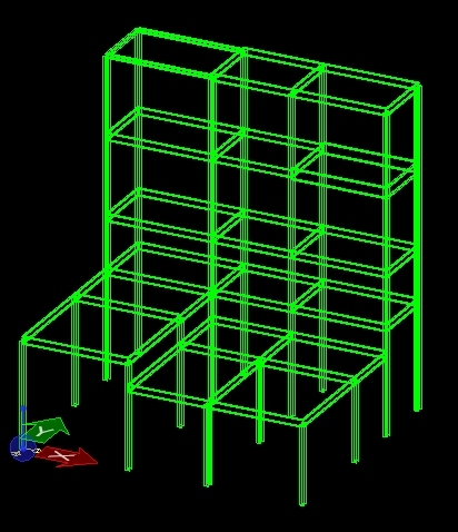
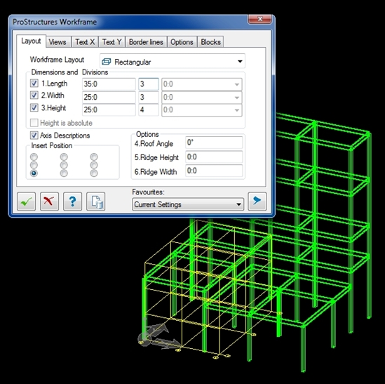
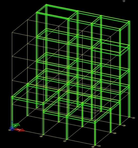
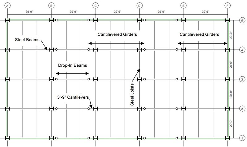
For this example we will look at a model that would need to have its beam members modified. This will demonstrate a way by which these beam members can be segregated easily so that we can select and manipulate them.

This is only one example of what this tool can be used for and that many other applications of the tool can be implemented if needed.

To begin with it should be noted that the search tool will only find elements that are visible, so be sure that the model in question is present and all the elements are showing


1.1  – Search Tool Location

1.1.1 - Finding the Search Tool

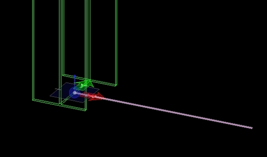
Here we need to start the Search tool. This is done by going to the ProSteel Edit ribbon area. (Note: Ribbon area screenshots are used for this document but the same method would apply from the available toolbars.)

Upon opening ProStructures for the first time the Positioning Icon will likely have focus and so we should locate this icon and display the flyout that appears beside it.

Coming down this flyout, at the bottom you should see an entry that looks like a magnifying glass. This is the Search Parts tool and you will need to click on this to open the Search Parts dialog window.


1.2 – The Search Parts Dialog Window

1.2.1 – The Dialog Window

The next this that happens should be a dialog window that has ‘ProSteel Search Parts’ displayed at the top left.

If not then go back to Section 1.1 and double check the steps you took to get to this point.


1.2.2 – Loading the Model Information

  When this dialog appears the very first thing you need to do is click on the exclamation mark icon at the bottom. This is important and needs to be done every time you open this dialog window for the tool to work. What this does is to look at the model and read all the information from the currently displayed elements; it then populates all of the Search tool fields with that information.


1.2.3 – Selecting What You Are Looking For

Once you have done this the next step is to decide what exactly you will be looking for. For the sake of this exercise we will be looking at the ‘orientation’ of the elements. I want to find everything that is horizontal or in essence a ‘beam’ orientation. To do this I look at the list on the list on the left hand side and select “Orientation type”.

Selections made from this list will affect the values available in the “Single Comparison” area of the dialog window (See 1.2.4).


1.2.4 – Developing A Single Comparison Argument


 In the “Single Comparison” section, you will notice that your selection from the previous step appears automatically as the first variable in this area.

The second variable which appears between ‘orientation type’ and ‘beam’ allows you to select equals, greater than or less than or any combination thereof (The ‘! =’ option means not equal). This is typically used where measurements are involved such as length or weight. For now we will leave this set to ‘=’.

The dropdown on the right is where you can select any variable relating to your initial selection, in our case ‘orientation type’. Here we will be selecting “Beam” from the dropdown.

The argument you develop here is what will be used to search for elements from within the model itself. Before accepting it, you can preview what you’ve developed as an argument directly below the dropdown boxes. If this is what you want to use then the next step is to accept it. Before doing so however it is important to verify that a previous argument does not already exist.


1.2.5 – Checking And Clearing Previous Arguments

Beow the ‘Single Comparison’ section you will see another section called ‘Complete Filter Expression’. It may reflect your current argument but if anything else appears here then it should be cleared prior to accepting the argument you are trying to develop.

 To clear the argument displayed in this area, left-click on the icon that looks like a funnel with an ‘x’ on the top right corner.

1.2.6 – Accepting You Argument

 Go back to the ‘Single Comparison’ section and left-click on the icon that looks like an arrowhead pointing down. This will accept your created argument and move it to the ‘Completed Filter Expression’ section. It is now ready to be used.


Additional Information:

You have the option at this point to develop more complex arguments by adding to your initial one by using the ‘And’ or ‘Or’ buttons. This will allow you to create a second argument and when accepted add this new argument to your initial argument, thereby creating a more complex expression.

For example “find all objects that are oriented like a beam ‘and’ are 20 ft. in length”. The elements in this case would need to meet both requirements. This could also have been done using ‘Or’. In this case it would become, “find all objects that are oriented like a beam ‘or’ are 20 ft. in length”. In this case all the beams would be found and all elements 20 ft. in length would also be located.

For the sake of this document however, we are only looking at our initial single argument of, orientation type equal to beam.

Make sure you have accepted this and move on to the next step.

1.2.7 – Assigning An Action

With the argument setup and ready to be used we now need to tell the tool what it should do once it has found the elements we are searching for.

Near the bottom of the dialog windows is a section labeled ‘Options’. The dropdown here provides four choices; Hide, Hide Other Objects, Mark and Zoom Extents. Depending which one is selected, that action will occur when the parts are found.

In this example we would be looking to ‘Hide Other Objects’, thereby leaving the ones we find as the only elements showing.


1.2.8 - Using The Search Function

 With all of the settings in place it is now time to use the search function. This can be accomplished by left-clicking on the checkmark icon in the bottom left corner of the dialog box.

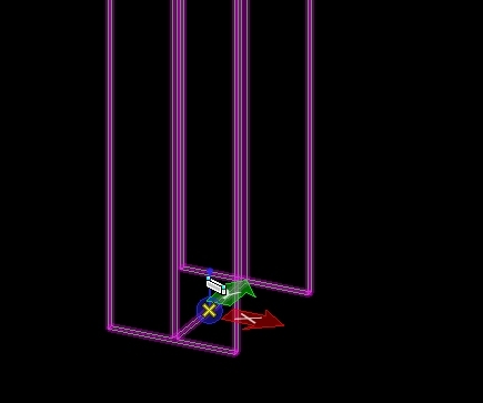
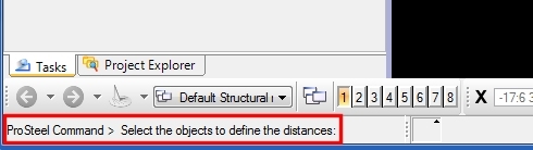
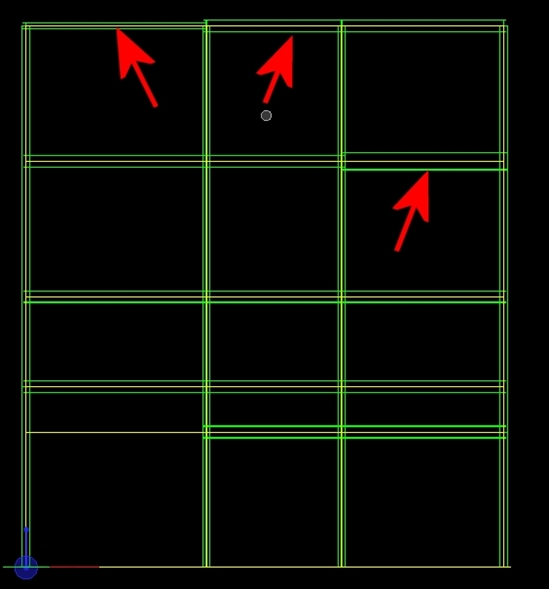
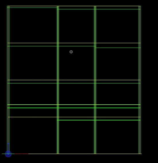
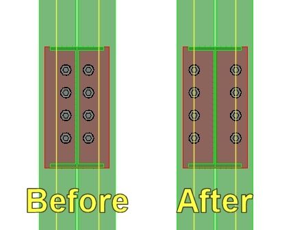
When this is done, the dialog box will disappear and you will be asked to select the area you want to perform your search in. This can either be a very specific area or simply by selecting the entire model if you prefer. In this case the entre model would be selected. Once all areas have been selected, right-click to complete the action. Anything that does not correspond to your argument should have disappeared, with the exception of some lines perhaps.


1.3 – Element Regeneration

1.3.1 – Showing The Elements When Done

Once you’ve finished working on the elements you can bring back all the ones that were hidden by the Search tool. To do this you need to click on the ProSteel 3D Regen icon.


 The ‘Regen’ icon can be found by going to the ‘Viewtools Ribbon’ and clicking on the flyout beside what would typically be the Display Class icon by default.

 On this flyout you should see what looks like a blue channel shape with ‘REG’ written in the middle. If you left-click on this icon, any item that was hidden during the use of the search command (or from using the hide tools prior to this) will be shown again.


Did You Know? RAM Connection Gussets and Base Plates

$
0
0

Did You Know… RAM Connection has an extensive library of connection types built into the program? I frequently am asked, "Can RAM Connection do [     ]?" where the blank is filled in by a specific connection type.

I previously wrote a couple of blogs discussing shear and moment connection types.  There are two additional connection types available in RAM Connection: gussets and base plates.  These connection types are equally important, and normally more difficult to design.  You may download a quick reference PDF of these connection types at the bottom of this blog post.

All gusset and base plate connections in RAM Connection are designated as “smart.”  If I lived in Boston I’d even call them “wicked smaht.”  A smart connection optimizes certain aspects of the connections, such as plate thickness, weld size, number of bolts, etc.  The optimized aspects vary depending on the template you assign.

So without further ado, here are the majority of the gusset and base plate connections available in RAM Connection.  This is not an exhaustive list.  RAM Connection is customizable and it would be difficult to list every single connection available.

Gusset Connections

     G1. Columns Beams Braces _ Double Angle

     G2. Columns Beams Braces _ Double Angle Continuous

     G3. Columns Beams Braces _ Single/Shear Plate

     G4. Columns Beams Braces _ Directly Welded

     G5. Chevron (Shown with Bolted Angles)

     G6. Vertical X-Brace

     G7. Columns Beams Braces _ Directly Welded _Concentric Braced Frame

     G8. Chevron_Concentric Braced Frame (Shown with Welded Tubes)

     G9. Gusset Base Plate – See Base Plate Connections


Base Plate Connections

     BP1. Pinned Base Plate

     BP2. Fixed Uniaxial Major Axis Base Plate

     BP3. Fixed Uniaxial Minor Axis Base Plate

     BP4. Fixed Uniaxial Both Axis Base Plate

     BP5. Fixed Biaxial Base Plate

     BP6. Gusset Base Plate (Shown with Welded Tube)


Announcement: ProStructures/ProConcrete's first online training

$
0
0

The first online training for ProConcrete on MicroStation will take place next week (from Sep. 17th to 18th). This training is from 8am to 5pm North American Eastern Time.

This will be delivered on the new release of ProStructures, V8i Ss6, which will be release Monday Sep. 16th on our SELECTserver.

Added note: There have been issues with the release of Ss6. It has been delayed a few days. Nevertheless the training will still take place using an internal build (Release candidate)

There is still time for you to register. Follow the link bellow and login to register.

­­>>> REGISTER HERE <<<

Other dates are available later in the year as you can notice at the bottom of the link.

Instructor changes: I will be delivering the 1st and 2nd of these trainings. My colleague Doug will be delivering the 3rd (and last one for 2013).


A Guide to RAM Concept Information on the Web

$
0
0

There is a wealth of technical resources available to our RAM Concept user base. Over the past several years our structural product experts have produced how-to video tutorials, product tours, and tech notes that address a wide range of topics and questions the RAM Concept user community commonly raises. Most, if not all, of this content resides on either our own BE Communities site or youtube. Up until now there’s been no single master list of RAM Concept product information. This post is a step in that direction. This list identifies and describes all the content we know to exist, and we'll continue adding to it and more effectively organize the items. Many thanks are in order to the contributors of this content, and in each landing site you’ll see the name of the authoring Bentley colleague. In the meantime feel free to pass along suggestions for content to me at Josh.Taylor@bentley.com.


RAM Concept Insider Skills

Part 1

http://www.youtube.com/watch?v=4NpdZrLBWLc

1)      Reconfiguring slab and load polygons by adding or removing nodes

2)      Refining and simplifying program-generated design strips (2:35)

Part 2

http://www.youtube.com/watch?v=mkSacbm0prA

1)      Interpreting errors and warnings during the analysis

2)      Reviewing the error log (2:20)

3)      Locating errors by coordinates (2:45)

4)      “Line is too short” error (3:30)

5)      Using perspective views to troubleshoot errors (5:16)

6)      Fixing the “Tendon is out of slab” error (6:01)

7)      Cross section trimming considerations (7:47)

8)      Effect of the cross section slope limit setting (13:25)

Part 3

http://www.youtube.com/watch?v=4_lKyouA1PI

1)      Reviewing slab precompression magnitudes using 2D plots

2)      Displaying slab stress plans for specific load cases (2:30)

3)      Simplifying the review of bar design results by varying display settings (3:45)

4)      Reviewing live load reduction values calculated by the program (7:18)

Part 4

http://www.youtube.com/watch?v=H2Np4_KIW5c

1)      Using the Cross Section Orientation tool to rationalize the placement of program-selected reinforcement

2)      Refining tendon layouts using the tendon void and tendon parameters commands (2:50)

3)      Analysis of floors for footfall vibration (8:00)


RAM Concept Tech Snippet: Tendon Tools

http://www.youtube.com/watch?v=Sv-LuqjVSIs

How to lay out tendons using the Generated Tendon method, a much quicker alternative to manually creating individual tendons.


RAM Concept Tech Snippet: Working with Reinforcing

http://www.youtube.com/watch?v=L2-F6-5oPe0

How to rationalize program placed reinforcement to a simplified layout.


Exporting a RAM Concept floor to RAM Structural System

http://www.youtube.com/watch?v=DU60wpCTEIY

A video demonstration of the export of a RAM Concept model into RAM Structural System for the multi-story analysis and design of the superstructure.


Designing Slabs in RAM Structural System

http://communities.bentley.com/other/old_site_member_blogs/bentley_employees/b/annmarie_garkohill_blog/archive/2013/02/15/designing-slabs-in-ram-structural-system.aspx

A quick start guide to utilizing RAM Concept as a module within RAM Structural System.


Animation of plots in RAM Concept

http://www.youtube.com/watch?v=_uLdA3lAwAI


Balance and Hyperstatic Loading

http://communities.bentley.com/products/structural/structural_analysis___design/w/structural_analysis_and_design__wiki/8068.aspx

A quick and effective explanation of balance and hyperstatic loads.


RAM Concept Capabilities and Modeling FAQ

http://communities.bentley.com/products/structural/structural_analysis___design/w/structural_analysis_and_design__wiki/2056.aspx

Some basic discussion on modeling limitations in RAM Concept.


RAM Concept Design Strips

http://communities.bentley.com/products/structural/structural_analysis___design/w/structural_analysis_and_design__wiki/4507.aspx

1)     Defining manual design strip boundaries

2)     Cross section trimming

3)     Design strips and slab openings

4)     Full width design strips versus column/middle

5)     Design strips for beams


RAM Concept Files FAQ

http://communities.bentley.com/products/structural/structural_analysis___design/w/structural_analysis_and_design__wiki/2057.aspx

Some notes on file management in RAM Concept, including mat files and CAD backgrounds.


RAM Concept Lateral Self Equilibrium Analysis

http://communities.bentley.com/products/structural/structural_analysis___design/w/structural_analysis_and_design__wiki/3086.aspx


RAM Concept Load History Calc Options

http://communities.bentley.com/products/structural/structural_analysis___design/w/structural_analysis_and_design__wiki/6191.aspx

A discussion of the settings and options in RAM Concept’s load history deflection analysis.

1)     Creep factor

2)     Shrinkage strain

3)     Shrinkage restraint

4)     Aging coefficient


RAM Concept Loading

http://communities.bentley.com/products/structural/structural_analysis___design/w/structural_analysis_and_design__wiki/3087.aspx

Information on some nuances of applying loads to the floor.


Getting More Out of Your RAM Concept Plots

http://communities.bentley.com/other/old_site_member_blogs/bentley_employees/b/annmarie_garkohill_blog/archive/2013/04/12/getting-more-out-of-your-ram-concept-plots.aspx

A review of important settings for control of plot information, color coding, and display style.


RAM Concept Plans and Perspectives

http://communities.bentley.com/products/structural/structural_analysis___design/w/structural_analysis_and_design__wiki/2058.aspx

Troubleshooting a few issues users have come across when viewing plans and perspectives.


Did you Know? RAM Concept Plans and Perspectives

http://communities.bentley.com/other/old_site_member_blogs/bentley_employees/b/beth_suminski_blog/archive/2013/06/14/did-you-know-ram-concept-plans-and-perspectives.aspx

How to customize plots in RAM Concept to show specific information according to your own preferences.


RAM Concept Reinforcing FAQ

http://communities.bentley.com/products/structural/structural_analysis___design/w/structural_analysis_and_design__wiki/8362.aspx

1)     Displaying governing code provisions

2)     Modeling of user reinforcing

3)     Suppressing additional program reinforcing during design

4)     Slab face setting for reinforcing

5)     Designing using a single reinforcing layer

6)     Customizing the bar callout style on the reinforcing layer


RAM Concept Shear Reinforcement

http://communities.bentley.com/products/structural/structural_analysis___design/w/structural_analysis_and_design__wiki/3094.aspx

Answers to commonly asked questions on shear checks and one-way shear reinforcement.


RAM Concept Structure

http://communities.bentley.com/products/structural/structural_analysis___design/w/structural_analysis_and_design__wiki/2059.aspx

Answers to a number of commonly asked questions dealing with the modeling and viewing of elements, fixities and restraint, and settings for soil in the design of mats and rafts.


RAM Concept T-Beams and Axial Forces

http://communities.bentley.com/products/structural/structural_analysis___design/w/structural_analysis_and_design__wiki/4412.aspx

An explanation of the significance of the T-beam setting for strip generation, and a quantitative illustration of how design forces are resolved when using this option.


RAM Concept Tendons

http://communities.bentley.com/products/structural/structural_analysis___design/w/structural_analysis_and_design__wiki/2060.aspx

Answers to commonly asked questions related to tendon placement, and how to resolve common warnings.


Intelligible Information Environments

blogging for multiple audiences

$
0
0

Earlier this year I started blogging also at another blog site. A smaller audience than here on Bentley Communities, but just another channel, and so far there have been readers from 64 countries.

Thank you for reading my posts!

Here is the other blog: http://dagsljus.wordpress.com/

An update to STAAD Foundation Advanced SS2 (version 6.2) is just released

$
0
0

The update (patch) of STAAD Foundation Advanced V8i SELECT series 2 (Release 6.2) is now available on SELECT to download. It is recommended for all users of STAAD Foundation Advanced version 6.2 to install this update package. This will update your existing 6.2 installation to the latest version.

To download the patch:

  1. Go to http://appsnet.bentley.com/myselectcd/ in your web browser.
  2. Select STAAD Products from the Products list.
  3. Select “All” in the Download Category list.
  4. Click Search. The list of all updates is returned.

  5. Select the appropriate patch (06.02.00.59) of STAAD Foundation Advanced V8i
  6. Click Continue and download the update installer.


Similar to previous updates, there are several enhancements and bug fixes included in this package. Here are examples of a few major enhancements.

Combined footing design moment calculation at column faces

This is an important and long pending item. Previous versions used to take maximum and minimum moment solely based on bending moment diagram and there was no check in place to ignore higher moment values underneath the column or pedestal. Now program automatically calculates moment at all column faces and ignores moment points underneath the columns. Previous approach sometimes could lead to more conservative design, so new version leads to a more realistic design.

Foundation design based on ACI 318 now supports 3 versions of the code

This feature was previously already added in “general Mode” but was missing in “Plant Mode” and “Toolkit Mode”. With this update package program will now support ACI 318-05, ACI 318-08 and ACI 318-11 for all modules of the program.

  
Enhanced spreadsheet import/export capabilities

Spreadsheet import/export is a popular feature in STAAD Foundation. This update added a few more tables to the import/export capabilities. The spreadsheet feature now supports ‘Soil Bearing Capacity Factor”, “Self weight factor” and new ACI 318 code version tables. Soil bearing capacity factor table is used to input load specific allowable bearing capacities. The best examples are load combinations involving temporary load cases such as wind and seismic. Many codes allow 33% increase of bearing capacity for wind and seismic load cases. An input of 1.33 against such load combinations in soil bearing capacity factor table will increase soil bearing capacity by 33%.


Automatic load combination generation based on ASCE 7-2010

ASCE 7-2010 table is now added as another option for automatic load combination generation. Many users requested for this tableas it is now being used as the standard load combination table replacing ASCE 7-2007 version. However, for the convenience of the users both versions of the load combination tables are supported.

New Input For Pedestal Steel % Reinforcement For US Code From Global Settings:

For the convenience of experienced users, required minimum and maximum % of steel for pedestals can now be directly specified. By default, the program will use code specified steel %. One might argue why a program would allow to modify code specified minimum/maximum steel. The answer points to the different design practices among different organizations around the world. However, those user specified % will be printed on the calculation sheet for review purposes.


This is probably the last and only update to STAAD Foundation Advanced SS2 (version 6.2). The next version of the program (version 7.0) is scheduled to be released by the end of this year which will include several exciting new features.

How to change unit in advanced units settings by keyin for MS v8 08.05.01.25

$
0
0

HI

I have microstation v8 version 08.05.01.25 installed. My problem is to find a keyin command to change the storage unit in advanced units settings.

Because i want to use this command/keyin in my Macro.

"SET STORAGEUNIT" doesn't work for my version.

Please help, I'm just waiting for this problem to be solve.

Tip No.8: Generating a Workframe around and existing structure

$
0
0

In this tip, I will show you how to get ProStructures to automatically recognise the steel elements (Beams & Columns) in a model in order to build the corresponding Workframe.

This could be used for example on a structure built in STAAD, imported into ProStructures using ISM to which we now want to add the Workframe.

First, be aware that any structure imported from STAAD will have all members inserted from their middle. Which means all beams will be "offset " half their height upwards. It is actually a "good" thing to have before executing this tip because the Workframe will be built at TOP of all COLUMNS & MID-LINE of all BEAMS.

Once you have the steel you want to create a Workframe around, start the workframe command and select the bottom of the front/left column (of the plan view orientation you want to create with the workframe) as the insertion point.

Then select the orientation of the X axis (bottom of plan view to be generated with this workframe)

At this point the Workframe dialog box will pop-up, showing the values used the last time you used the Workframe, which obviously do not correspond to this specific structure.

Make sure you UNSELECT the 3 check boxes at the left hand side of the Layout tab as shown below in order to activate the "manual" entry of distances.

Now expand any of the 3 pull-downs, and anywhere inside the pull-down, left click with the mouse WHILE holding down the left hand side of the keyboard CTRL key.

You should now be prompted to select the items you want to consider in order to build this new Workframe. Select the whole structure.

Notice how all lines of Workframe appeared (as mentioned in the beginning) in the middle of all beams and on top of all columns. Now we can move those beams back down to their top of steel.

Select ALL beams, and get their "PS Properties" dialog box to open. In the Position tab, notice how their insertion point is the middle. Simply select the top of steel and all beams will shift up by half their height regardless of the fact they are not all the same height.


Proyecto Hidro

$
0
0

Buenas, estoy iniciando en el aprendizaje de Hammer, ya que me lo recomendaron para el analisis de trancendentes, entonces me surgen las siguientes dudas:

1.Necesito colocar una reduccion de diametro, pero no se si el programa tendra algun item especial para esto, o si en el inicio de la tuberia con el diametro ya reducido se puede colocar algun coeficiente de perdida localizada

2.hay un punto donde mi tuberia se bifurca para ingresar con distintos caudales hacia las turbinas, existira alguna libreria con items como estos.

3. tengo elementos de desacarga que en otros paquetes como WHAMO ( del US ARMY), en el que se definen elementos Dummy, los cuales no tienen una definicion fisica, entonces quisiera saber si existe alguna forma similar de imitar el codo de aspiracion o la descarga hacia el siguiente reservorio es directamente.

Gracias de antemano por su colaboracion.


SS5 - Stretching / Altering Bay Sizes

$
0
0

With Interfering Elements

When a model is built, if for some reason the bay size needs to be altered after the miscellaneous steel has been placed, then altering the model may become a bit more difficult. The reason for this being that not all miscellaneous steel will react the way the user is expecting. One example of this would be bracing elements created using the commonly used dynamic bracing command. In this example bracing elements are parametric objects that are tied to the line or points originally selected when placing the elements.

Even though the parametrics of the object will allow for certain automatic updating functions to take place, radical changes like bay sizes may require that the parametric objects in question be replaced.

Using the bracing example mentioned above, the easiest method of doing this is to create a template from the parametric dialog window, remove the original elements and place them again using template to automatically setup the elements to their original state.


Cut lines or post modifications will also need to be repeated in this case.

Without Interfering Elements

If you do not have any interfering elements then a simple stretch command can be used to enlarge a bay area.  This will stretch the members in the selected area, along their current path to any length required. It should be noted however that if a workframe was used, then this will need to be modified afterwards from the workframe dialog window to match to new model sizes.

In a situation like this, stretching the elements along their existing path will simply enlarge the bay area without any adverse effects.

Three things should be kept in mind however when using this method.

  1. All items should be showing. Anything hidden or not showing for whatever reason will not be stretched.  Turn on layers that contain elements, ‘regen’ items that are hidden, display and area class objects should all be showing and clipping planes turned off. The use of any or all of these functions will cause the hidden objects to not be affected by the stretch.
  2. All objects will be stretched along their current path. If horizontal members are being stretched then this method should work fine but keep in mind that if something is angled that the members will not follow the horizontal shift but rather will continue to extend along their current course to the new point selected by the stretch command.
  3. The workframe itself should not be selected. The reason for this being that the workframe lines will be moved from its original location and not stretched. For this reason when selecting the elements to stretch, deselect the workframe lines before actually stretching the members themselves.


NOTE: The upcoming MicroStation version of SS6 may include code that allows the MicroStation stretch tool to better handle the stretching functions of ProStructures elements.


Tip No.9: Using the ProStructure Snaps on Ss6 (MicroStation release only)

$
0
0

This tip only applies to the MicroStation version of ProStructures SELECTseries 6 (not release yet)

With ProStructures SELECTseries 6 for MicroStation, you will notice a new page available in the Global Settings called "Snaps".

In this page you have the option to enable what is called the "ProStructure snaps" or the "ProStructure legacy snaps" and to enable the "ProStructure tooltip" as well.

What happens if I don't activate any of the two snaps? What is the difference between the two snaps? What is the tooltip for? I'll explain this in this tip.


Q.1) What if I don't use neither of the snaps?

A.1) In this case you will be using the standard MicroStation snaps. The Tooltip option, even if enbled will not display.


Q.2) What do the ProStructures snaps do?

A.2) When activated the selection of insertion points will forget the MicroStation snaps and use the shape's start point, end points and mid point to distribute.

You can change these to the MicroStation "Keypoint Snap Divisor" by pressing the "K" key and selecting the number of division you want. For example 6 in the image bellow.

You will also get the option to flip from all 10 available snaps points at each division point allong the shape using the keyboard Arrows, PageUp, PageDown, Home & End keys.

The keys do the following:

  • Arrow keys = "up/down" (1-4-7 if starting at point 1) or "left/right" (1-2-3 if starting at point 1)
  • Page Up/Page Down = cycles between ALL points sequentially
  • Home = goes to the insertion point
  • End = goes to the center of gravity (point 10 in the image above if the element is an angle)


Q.3) What do the ProStructures legacy snaps do?

A.3) When using only legacy snaps, you will get standard MicroStation snaps and centerline snaps at both ends and divisions (MicroStation "Keypoint Snap Divisor" once again) of the shape.


Q.4) What is the tooltip and how do I customize it?

A.4) When activated the tool tip will show while selecting insertion points. The information shown by default is the following:

This infornation can be customized by editing the tooltip.ini file located in the PRG folder.

Lets say we want to change the tooltip to show the name, length, material & description index.

This is the original line we would need to change:

Form=Postion=%POSITION%\nPickPoint=%PICKPOINT%\nType=%TYPE%\nShapeName=%NAME%\nZcoordinate=%ZCOORDINATE%

This is the new line to use:

Form=Name=%NAME%\nLength=%LENGTH%\nMaterial=%MATERIALNAME%\nFDF=%FREEDESCRIPTION%

 Note: In order to get a better result with these snaps it is suggested to be in wireframe mode.


What's new in LEAP Bridge Enterprise V8i (SELECTseries 6) v13.00.00.68?

$
0
0

LEAP Bridge Enterprise V8i (SELECTseries 6) v13.00.00.68 ReadMe


Version

V8i v13.00.00.68 (SELECTseries 6)

Operating
Systems

Windows 7

Language

English


Before you begin, please note the following:

  • Review the End-User License Agreement (or EULA) carefully during the installation of LEAP Bridge. By installing this release, you agree to the terms and conditions of the agreement. A copy of the End User License Agreement named EULA.pdf will be included in the "\LEAP Bridge Enterprise\eula.pdf" folder of the product installation. By default, this location is "C:\Program Files\Bentley\LEAP Bridge Enterprise."
  • Before installing LEAP Bridge, be sure to fully read this document as well as the Installer Note  where you can find critical information important to your installation.

This document contains the following information:


What is New & Changed?


CONTENTS 

  • LEAP Bridge Enterprise v13.00.00.68
  • LEAP CONSPAN v13.00.00.68
  • LEAP CONBOX v13.00.00.68
  • LEAP RC-PIER v13.00.00.68
  • LEAP GEOMATH v13.00.00.68
  • Upgrade Instructions

LEAP Bridge Enterprise V8i (SELECTseries 6) v13.00.00.68 incorporates the following enhancements and fixes to itself and its component programs:

LEAP Bridge v13.00.00.68

Enhancements:

  • Several enhancements to the ABC Wizard including new options for
    • Combined footing definition
    • Advanced definition of girders, different beam types in spans
    • Advanced definition of girders, different start and end distances in a span
    • Advanced definition of piles and customization of x and z for layout and batter direction specification, for both abutments and intermediate piers.
    • Program now allows user to specify unit prices for materials and computes and reports estimated quantities and cost for bridge.
    • On 3D model export to DGN, EC properties (dimensions, IDs, material properties) are written out as well.
    • Introduced a new bridge type cast-in-site post tensioned I-girder bridge for the India code option.
    • New workflow introduced so that after changes are made in GEOMATH and the model is updated to LEAP Bridge, users can still go into CONSPAN and RCPIER and make geometry changes.


Fixes:

  • Span beam seat elevation report now displays the elevation at the top of the seat rather than bottom at cap level.
  • Several 3D graphics issues have been fixed including incorrect section variation orientation for skewed flat slab and box girder bridges.
  • Fixed issues with integral pier elevation computation when superstructure has a cross-slope defined.
  • Fixed issue with bridge deck start and end when viewed in Geomath for offset bridges on curved alignments.
  • Fixed issue with editing of bridge element names directly in tree view on the Geometry tab.
  • Schematic curbs are drawn in bridge section views, even when curb is less than 1.5 ft.
  • Corrected H-pile orientation in 3D and 2D view drawings.


LEAP CONSPAN v13.00.00.68

Enhancements:

  • CONSPAN now offers a new option to consider sacrificial deck thickness in computation of LRFD live load distribution factors.
  • CONSPAN offers an option to allow users to not include the reduction of live load distribution factors for moment in longitudinal beams on skewed supports.
  • Load rating summary table now reports prestressing strand tension (PSStT) if selected for rating analysis. The computation of PSStT has been modified to follow the procedures of the MBE, section A3.13.4.2.b.
  • For Canada code option, comprehensive load evaluation of prestressed girders per Chapter 14 of CSA S6-06 is now offered.
  • New unified Help file replaces the previous user manual Volume 1.


Fixes:

  • Rotations due to live loads were incorrect and have been fixed.
  • Fixed the following Vertical Shear issue: When the option to use Simplified Shear procedure (LRFD article 5.8.3.4.3) was used, the design shear Vu was incorrectly using the shear corresponding to the maximum moment rather than the maximum shear.
  • Live load distribution factor for multi-stemmed beams: When using Lever Rule the distribution factors were computed incorrectly by considering the distance from the edge of curb to the center of exterior web rather than to the center of the beam. This issue is now fixed.
  • Shear Rating factors computed with the FLDOT option for counting shear stirrups across failure plane turned on, and simultaneously the simplified shear design procedure was used were incorrect. This issue is now fixed.
  • The connection from CONSPAN to AASHTOware Virtis/Opis v6.3 was rewritten to make it more stable and easier to update in to newer versions in future releases.
  • A new warning message highlighting current program assumptions on flared (or non parallel beam arrangement) is now displayed when the run analysis button is pressed.
  • For Canada code option, minor bug fixes include
    • Deflection computation has been updated to use distribution factor for Moment, and considers the dynamic allowance for Truck.
    • Horizontal shear required vs. provided graph was using incorrect unit conversion, and was corrected.
    • Dead Load reactions were not multiplied by ULS value under ULS printout. Fixed now.


LEAP CONBOX v13.00.00.68

Enhancements:

  • Post-tensioned I-girder bridge for CONBOX India:
    • Simply-supported parallel girders on straight alignments
    • Multi-stage post-tensioning
    • Parametric cross-section definition for I-girders
    • Library of cross-sections to choose from
    • End block and taper section definition
    • Elastic shortening, Concrete creep and shrinkage, and steel relaxation losses in post-tensioning tendons per IRC
    • Deflection calculation, stress checks, and shear and moment capacity calculations per IRC

Fixes:

  • For CONBOX US: Corrected values of a, c, b, bw reported in the detailed moment capacity report for the California option.
  • For CONBOX India: Resolved discrepancy in the permissible shear stress values shown in Design Parameters and the ones actually used in design.


LEAP RC-PIER v13. 00.00.68


Enhancements for US, Canada, and India:

  • Flexural design is now offered at user-defined points of interest along pier columns and drilled shafts.
  • Export selected analytical results of all load combinations with or without P-Delta effect to spreadsheet.
  • Reformatted the pile reaction and combined footing reports for clarity.
  • Option to reset loads and load combinations when changes to model are made.
  • Option to retain existing live load cases when the impact factors are changed.
  • Load effects are now calculated and reported at bottom of footing for the spread footing option.
  • Single row of piles can now be designed as reinforced concrete members.
  • Improved graphic view of shear reinforcement in pier columns.


Additional enhancements for US:

  • New features for California Option:
    • Out-of-plane load distribution.
    • Creep and shrinkage load generation.
    • Auto generation of wind pressure on structures as per FDOT Structures Design Guidelines. To activate this feature select WS as per FDOT SDG 2.4 under Loads tab.
    • Optimized the P-Delta analysis to substantially reduce execution time.


Additional enhancement for Canada:

  • Auto-generation of vertical wind load.


Additional enhancement for India:

  • New workflow for steel reinforcement in column auto design.


Following issues were fixed for US, Canada, and India:

  • Incorrect load effects were calculated in combined pile footing and combined spread footing.
  • Incorrect calculation of exposure height of substructure in auto generation of wind pressure on structures.
  • Incorrect load factor for the self-weight in combinations not involving DC load.
  • Incorrect moment of inertia reported in the stepped cap design.
  • Incorrect calculation of self-weight of stem wall for abutments.
  • Inconsistent bearing offset for abutments between LEAP Bridge and RC-PIER.
  • Incorrect orientation of H-piles in 3-D graphic view.
  • Displacements and rotations were incorrectly reported under “Show P-Delta Effects” option.
  • Incorrect 3D view of Cap Loads in y-direction.
  • Incorrect 3D view of Column Loads.
  • Incorrect governing load combination for footing design for “User specified maximum soil reaction” or “User specified maximum pile reaction”.
  • Incorrect load effects were used for footing design.
  • Incorrect calculation of CG of pile group for abutment piles with variable spacing.


Additional issues fixed for US:

  • Moment magnification did not work for the footing design.
  • Incorrect load factors of vertical soil pressure load (EV).
  • Incorrect label for the fatigue load combination.
  • Incorrect reactions at intermediate piers under the Integral Abutment option.
  • Vertical soil pressure load (EV) was incorrectly applied in case of multiple spread and pile footings.
  • Load effects were incorrectly combined when EH, EV, or LS load cases were used in design.
  • Incorrect coordinates in footing design report due to inconsistent sign convention between the global and local coordinate systems.
  • Incorrect multiple presence factor for permit live load was used for California option.
  • Truck and lane loads didn’t go together in live load auto-generation for LRFD-California option.
  • Incorrect red flagging in cap and footing design reports.
  • Crash when printing Analysis results for controlling load combinations for abutments.
  • Incorrect controlling load case was used for “Extreme Event Seismic” load group.


Additional issues fixed for Canada:

  • Incorrect auto-generation of live load as per Canadian Highway Bridge Design Code (CHBDC).
  • Incorrect auto-generation of fatigue load check as per CHBDC.
  • Incorrect data transfer and warning messages when the reaction data file generated by CONBOX were imported into RC-PIER.
  • Incorrect reactions at intermediate piers under the Integral Abutment option.
  • Incorrect multi-lane loading factors in design report.


Additional issues fixed for India:

  • Failed to auto-generate live loads for “Compute Simple Span Reaction” or “Compute Continuous Beam Reaction” options.
  • Incorrect auto-generation of temperature load.
  • Incorrect report when seismic loads were included in substructure design.
  • Corrected column design using reduced permissible stress method.

Geometry Module: GEOMATH v13. 00.00.68


Fixes:

  • Minor fixes to accommodate changes in LEAP Bridge

Upgrading from LEAP Bridge Enterprise

  • Follow the on-screen instructions and install the program.
  • The program will automatically be installed in the existing LEAP Bridge Enterprise folder.
  • During installation, program default libraries will be added under “C:\ProgramData\Bentley\LEAP Bridge Enterprise\” folder to comply with Windows standards to eliminate problems with access to users without Admin privileges.
  • The installation program will not overwrite the files already existing in the library folder.
  • If you have customized program libraries, you can move them to the above folder, and set the correct paths in the Library Setup dialog from within LEAP Bridge interface.

Installer Note

How to install & activate LEAP Bridge V8i (SELECTseries 6)?

Contents:

  Installation Wizard

  Activation wizard


This section guides you through the process of installing LEAP Bridge on your computer. In order to install LEAP Bridge V8i, please login as an Administrative user. LEAP Bridge can be installed by invoking Setup.exe. If you use Setup.exe, no other special consideration is necessary. Simply follow the instructions that follow. For details on the installation, please refer to the Installation Wizard section in this manual. Note: LEAP Bridge V8i requires Microsoft .NET 3.5 framework to be installed in order to operate properly.

Installation Wizard:

  • First log into the Bentley SELECT Services Web site (http://selectservices.bentley.com) and download the LEAP Bridge installation kit for the version you have purchased. Please do not download the individual components (such as CONSPAN, RC-PIER, etc.) if you intend to install LEAP Bridge. The LEAP Bridge Enterprise installation package includes the necessary components.
  • Once you have downloaded the LEAP Bridge Enterprise installation files, locate the install folder. Run the installer file by double clicking the setup.exe icon.
  • You will be greeted by the Welcome screen. Click Next> to proceed with the installation process.
  • You are now presented with the End User License Agreement for this software. Please read the agreement and then click the radio button to accept the terms when finished. You may also print a copy for your records. Click Next> to continue.
  • You will be asked for an installation location. This is the directory location of the program on your computer.
  • The installer now has gather all the information needed to complete the installation. Click Install to finish the process. The wizard begins installing the program onto your computer. Once the process is complete, click Finish to exit the Wizard..
  • After the installer completes its process, the program is ready for use. You can launch the program by clicking the Start button and then All Programs > Bentley > LEAP Bridge Enterprise.

Note: Until you have activated a license for the program, it will remain in demo mode and function for only 15 days past installation.

Activating a product using the Product Activation Wizard

This is for installations which use a Bentley Server to authenticate the Bentley SELECT License used to run LEAP Bridge. In order to complete the installation, the SELECT Server Name and Site Activation Key will be required. If you do not have these, please contact Bentley technical support. Without this information the installation will operate using a trial license for only 15 days.

  • Install LEAP Bridge Enterprise following the instructions in the Installation section.
  • Locate the Bentley SELECT License Management Tool, LicenseTool.exe in the program installation folder (typically the location is c:\Program Files\Bentley\LEAP Bridge Enterprise\).
  • Select the SELECT subscriber activating against a hosted (Bentley) SELECT Server option and then click the Next > button.
  • The dialog box displays with the Server name provided for Bentley’s server. Complete the Site Activation Key received from Bentley and click the Next > button. Before accepting the entered information, you may also choose to click the Test Connection button to confirm that the entries are correct.
  • Enter the SELECT Server name and the Site Activation Key received from Bentley, and click the OK button. If you do not know these, please contact your system administration. Before accepting the entered information you may also choose to click the Test Connection button to confirm that the entries are correct.
  • After the information is accepted by the system, the program then displays all the available licenses for your usage as shown in the following dialog box. The license security is now in place. The installation is complete and LEAP Bridge is ready for use.

Note: You may need to contact your system administrator if your organization uses a proxy server to connect to the Internet. Click the Proxy... button in the Product Activation Wizard to display a dialog for entering these connection settings.


Directory Structure

The default directory of LEAP Bridge is "C:\Program Files\Bentley\LEAP Bridge Enterprise\", if the user has not changed the location during installation. The tutorials are installed in the Example directory within LEAP Bridge folder. Help directory within LEAP bridge folder contains all the necessary help files for individual components. Lib folder contains the default library files for rebars, tendons, cross sections. It is recommended not to delete the default library files. Starting with v12.01.00.57, there is a change in the location of the library files. During installation, program libraries will by default be added under “C:\ProgramData\Bentley\LEAP Bridge Enterprise\” folder to comply with Windows standards to eliminate problems with access to users without Admin privileges. If you have customized program libraries, you can move them to the above folder, and set the correct paths in the Library Setup dialog from within LEAP Bridge interface.


Support and Services Information

FAQs, What's New/Changed and other technical information can be found on Bentley's technical support documentation page as well as the Bentley Library.

You can efficiently log issues that you encounter in Bentley products with the Service Ticket Manager. Information on other professional support and service offerings from Bentley is available online at SELECTservices Online.


Using the Online Help

LEAP Bridge features a user manual available in .chm format. A pdf version of the step by step guide to the tutorials is also provided. Tutorial files are located in Example directory. Adobe® Acrobat Reader® is required to use the pdf tutorial manual. Acrobat Reader is a free download available at www.adobe.com. The installation process will automatically install the user manual for LEAP Bridge and each component application (GEOMATH®, CONBOX®, CONSPAN® and RC-PIER®) in the Help folder. To access the manual and tutorials, select the appropriate link from the Help menu. 

Colaboración en un proyecto BIM - ¿Posible o Imposible?

$
0
0

Todos los que de una manera u otra nos relacionamos con la tecnología BIM nos hemos hecho alguna vez la misma pregunta: ¿Es posible de verdad trabajar con BIM en un entorno colaborativo? Como podéis suponer, la respuesta no puede estar basada en un software o una aplicación concretos, sino en una metodología de trabajo, que funcionará en mayor o menor medida dependiendo del grado de implicación de cada uno de los participantes y del grado de interoperabilidad de cada una de las aplicaciones que utilicemos. Y entonces, ¿Cuál es la respuesta? ¿Sí o no? Cómo bien os imagináis, la respuesta es SI. ¿Y cómo se pone en práctica? Pues eso es lo que voy a intentar explicar en este artículo.


Colaboración Multidisciplinar

El primer punto sobre el que crear el entorno de colaboración aparece durante la fase de diseño. ¿Cómo pueden trabajar el arquitecto, el ingeniero de estructuras, el de instalaciones de fontanería y ventilación y el responsable de las instalaciones eléctricas en paralelo, sin límite de usuarios accediendo simultáneamente al proyecto, y en cualquier tipo de proyecto, por muy grande que sea? Si pensamos en una única herramienta, que nos ofrezca toda la funcionalidad necesaria sea cual sea nuestra disciplina, que soporte desde el primer modelado hasta la generación de render fotorrealísticos, y que se pueda iniciar con diferentes perfiles, de tal modo que el interfaz de usuario se ajuste en cada momento al usuario que la está utilizando, entonces la mejor opción se llama AECOsim Building Designer, la aplicación de diseño BIM de Bentley. Su propuesta de gestión del modelo BIM de modo "federado" o distribuido permite al responsable del proyecto organizar los datos del mismo con su propia metodología de trabajo, y no se verá obligado a trabajar en el modo o manera que el software le imponga.


 Sección multi-disciplinar de un modelo con AECOsim Building Designer


Si potenciamos al equipo de diseño BIM con un "entorno gestionado" diseñado específicamente para colaboración en proyectos, como ProjectWise, estaremos ampliando el radio de colaboración a cualquier punto en el planeta. Para hacerlo, no necesitáremos tener una conexión de red directa entre los diferentes participantes en el proyecto para poder trabajar “conectados”, sino simplemente una conexión a Internet. Utilizando ProjectWise con el flujo de trabajo acordado, el equipo del proyecto siempre estará seguro de que el arquitecto estará trabajando en su modelo, pero viendo la última versión del modelo o modelos estructurales y viceversa, asegurándonos de que nadie tiene datos desactualizados. Cuando cualquier otro participante en el proyecto modifique datos que afectan al  trabajo de otros, ProjectWise enviará una notificación, y en ese mismo instante cada uno de los afectados podrá elegir ver la versión actualizada del modelo.

Aviso de cambios en el modelo, con AECOsim Building Designer y ProjectWise


Colaboración entre diferente software de diseño BIM

Todo lo que he contado hasta ahora es el método lógico si todos los participantes del proyecto utilizan software del mismo fabricante, y podemos pensar que si es así siempre va a funcionar, pero… ¿Por qué nos tenemos que ver obligados a elegir una herramienta sólo porque es la que utilizan los demás? ¿No podríamos trabajar en un proyecto utilizando una herramienta para el diseño de la arquitectura (por ejemplo, ArchiCAD, Allplan o SketchUp), otra diferente para el diseño estructural (AECOsim Building Designer, Revit o CYPE), y otra diferente para el diseño de instalaciones eléctricas y mecánicas (por ejemplo, AECOsim Building Designer)? ¿Y podríamos ser capaces de generar planos, secciones, alzados, del modelo completo? ¿Y podríamos generar un listado de inventario o de costes de todo el modelo? Aquí la respuesta vuelve a ser SI, y la solución tiene 2 nombres: i-model y Bentley Navigator, donde i- model es un formato de archivo de revisión que vamos a poder publicar, directamente desde AECOsim Building Designer y Revit, o a partir de un IFC generado con ArchiCAD, Allplan, CYPE o cualquier otra aplicación compatible con IFC, y donde Bentley Navigator es la herramienta que nos va a permitir hacer la revisión, imprimir planos y generar renders, animaciones, informes y documentación del proyecto completo utilizando dichos i-models.

Bentley Navigator mostrando una sección multidisciplinar


Colaboración entre Diseño e Ingeniería

¿Quién ha pensado que un programa de cálculo de estructuras o de cálculo de fluidos no forma parte del BIM? Espero qué nadie, porque si es así, los ingenieros responsables de estas áreas se van a enfadar con nosotros, y con razón. Por supuesto que forman parte, y nuestro compromiso debe ser involucrarles dentro del proceso BIM, porque no debemos olvidar que nunca tendremos un buen modelo estructural o de instalaciones si no hay detrás un buen programa de cálculo. Así qué, ¿Cómo lo hacemos? Lo que necesitamos es que haya una vía de comunicación bidireccional entre las aplicaciones de diseño y las de cálculo, bien porque sean capaces de interpretar el mismo formato de archivo (como hacen AECOsim Building Designer, STAAD, RAM, ProStructures y Tekla con el formato ISM) o bien, si esto no es posible, utilizar  un estándar de intercambio adecuado para la disciplina en la que estemos trabajando (CIS/2 y SDNF para estructuras de acero, por ejemplo, sin olvidarnos del IFC, que nos va a permitir compartir información de cualquier disciplina). El objetivo final de esta colaboración es que nunca haya que modelar o diseñar los mismos datos 2 veces, y si por ejemplo, el programa de cálculo de estructuras ya tiene un modelo generado con toda la información ***ítica de secciones, nodos y cargas, seamos capaces de generar el modelo físico importando los datos estructurales en la aplicación de diseño BIM.


Modelo Estructural importado de un programa de cálculo con AECOsim Building Designer


Colaboración entre Diseño, Revisión y Simulación del Proyecto.

Llegamos a uno de los momentos clave en el proceso BIM: La revisión del modelo multidisciplinar. Si después de todo lo que hemos trabajado para crear el modelo BIM, ya sea con una o varias herramientas, no somos capaces de utilizarlo para hacer una buena revisión y detectar los posibles problemas o interferencias antes de llegar a la obra, tenemos que replantearnos si de verdad estamos aplicando la metodología BIM correcta a nuestro trabajo. Cuando hablaba anteriormente de la colaboración entre diferentes aplicaciones de software, ya introduje el concepto de i-model y os hablé de Bentley Navigator. Esta aplicación va a servir para revisar visualmente el modelo, que puede haberse diseñado completamente con AECOsim Building Designer o utilizando otras aplicaciones BIM, pero también nos va a permitir hacer detección de choques entre elementos de la misma o de diferentes disciplinas, hacer comentarios (redlining) y que el responsable del diseño pueda visualizarlos en su propia aplicación, e incluso vincular tareas con elementos y/o conjuntos de elementos para hacer una simulación del proceso de construcción. La versión de Bentley Navigator para tabletas (disponible en IOS y próximamente en Android y Windows 8) nos permite realizar la revisión en campo y hacer comentarios a partir de los mismos i-models.


Bentley Navigator haciendo detección de choques multidisciplinar


Colaboración entre Diseño y Explotación (Facility Management)

Para acabar, el objetivo que nos deberíamos marcar cuando hacemos un proyecto BIM es el de que el modelo al que hemos dedicado tanto mimo y esfuerzo sea utilizable también durante todo el ciclo de vida del edificio, es decir, que pueda ser utilizado por un sistema de gestión y explotación (Facility Management). Si el modelo de diseño original puede ser utilizado sin necesidad de cambiar de formato (como hacen AECOsim Building Designer y Bentley Facilities, que trabajan sobre el formato DGN), pues perfecto, pero si no es posible, volveremos a abrir el debate de la interoperabilidad, estándares de intercambio y aplicaciones "abiertas" o "cerradas". Para cerrar el círculo, Bentley ha hecho un nuevo esfuerzo con la nueva versión de AECOsim Building Designer, y además de todos los formatos de intercambio que ya soportaba, ha añadido la interoperabilidad con COBie, que viene a sumar un documento Excel con toda la información del proyecto, según la definición establecida en el formato COBie, a la geometría y los datos almacenados en el formato IFC.


AECOsim Building Designer exporta a formato COBie


Enlaces relacionados:

AECOsim Building Designer: http://www.bentley.com/es-ES/Products/AECOsim+Building+Designer/

ProjectWise: http://www.bentley.com/es-ES/Products/projectwise+project+team+collaboration/

Plug-in para generar i-models desde Revit: http://www.bentley.com/es-ES/free+software/

Bentley Navigator: http://www.bentley.com/es-ES/Products/ProjectWise+Navigator/

Bentley Navigator para iPad: http://www.bentley.com/es-ES/Free+Software/Navigator+Mobile.htm

Bentley Facilities: http://www.bentley.com/es-ES/Products/Bentley+Facilities/


Autor: Eduardo Cortés (@_EduardoCortes)

Collaboration on a BIM project. Possible or Impossible?

$
0
0

Everyone that has been involved with BIM technology in one way or another, has heard the same question: Is it really possible to work with BIM in a collaborative environment? As you can guess, the answer is not based on specific software or application, but by defining a process that will work, depending on the degree of involvement of each of the participants and the degree of interoperability of the applications we use. What is the answer? Yes or no? You are right, the answer is YES. So how is implemented? Well, that's what I will try to explain in this article.


Multidisciplinary collaboration

The first step to create the collaborative environment is during the design phase. How can the architect, the structural engineer, the mechanical engineer, and the electrical engineer work in parallel, with unlimited users simultaneously accessing the project, for any kind of project, regardless of how big it is? If we think of a single application, providing all the functionality needed for whichever discipline, supporting the design workflow from the first sketch to the generation of photorealistic images, and be available to be accessed via different profiles, so that the user interface is directly applicable to each different user, then the best option is called AECOsim Building Designer, the BIM design software from Bentley. Its federated modelling approach to BIM allows the project manager to arrange the project data with their own specific workflow, and not be forced to work in the mode or manner that the software imposes.


Section of a multidisciplinary model with AECOsim Building Designer


If we empower the BIM design team with a “Managed Environment" specifically designed for collaborative projects, such as ProjectWise, we will be able to expand the collaboration radius to any point on the planet. For this, the team will not need to have a direct network connection between the individual participants on the project, but just an Internet connection. By using ProjectWise with a relevant workflow supporting the agreed information issue cycle, the project team will always be sure that when the architect is working on his project model(s), is able to see the latest version of the structural model(s) and vice versa, ensuring that no data is outdated. When any project participant changes data that affects others work, ProjectWise will send a notification informing them that more up to date information is available, and at that point they could choose to see the updated version of the model.


Notice of changes in the model, using AECOsim Building Designer and ProjectWise


Collaboration between different BIM design software

What I have described so far, is a logical method if all project participants use software from the same vendor, and we can believe in that way it will always work, but… why should we be forced to choose another tool because it's used by others? Can we not work on a project using separate tools for designing the architecture (e.g. ArchiCAD, Allplan or SketchUp), a different one for structural design (AECOsim Building Designer, Revit or CYPE), and a different one again for electrical and mechanical design (such as AECOsim Building Designer)? Would it be possible to generate drawings from the full model? And a bill of quantities or a cost report could be generated from the whole model? Here, the answer is again YES, and the solution has two names: i-model and Bentley Navigator. Where i-model is a review file format that can be published directly from AECOsim Building Designer and also Revit or via an IFC generated with ArchiCAD, Allplan, CYPE or any other application that supports IFC, and where Bentley Navigator is the tool that will allow us to do the review, print drawings and generate renderings, animations, reports and documentation  from the complete project, using these i-models.


Bentley Navigator showing a multidisciplinary section


Design and Engineering Collaboration

Who ever thought that a structural or fluid calculation program is not part of the BIM process? I hope no one, because if so, the engineers responsible for these aspects will not be happy, and rightly so. Of course they are a part, and there should be a commitment to involve them in the BIM process, because we must not forget that we will never have a good structural or mechanical model if there is not a good calculation program behind it. So how do we do it? What we need is a bidirectional communication channel between design and calculation software, either because they are able to interpret the same file format (as AECOsim Building Designer, STAAD, RAM, ProStructures and Tekla do with the ISM format ) or, if this is not possible, to use an appropriate exchange standard for the discipline in which we are working (like CIS/2 and SDNF for steel structures, for example, not forgetting IFC, which will allow us to share information from any discipline). The ultimate goal of this collaboration is to never have to model or design the same data two times, and if (in example) the structural calculation software has generated already a model with all the analytical information (sections, loads, nodes), we must be able to create the physical model by importing the structural data into BIM design application.


Structural Model imported from a structural calculation program using AECOsim Building Designer


Collaboration between Design, Project Review and Simulation.

We have reached one of the key moments in the BIM process: The multidisciplinary model review. If, after all that we have worked to create the BIM model, either with one or more tools, we are not able to use it to perform a good review and identify potential problems or interferences before coming to construction, we need to rethink whether we are really applying the correct BIM methodology. When I spoke earlier about the collaboration between different software applications, I introduced the i-model concept and Bentley Navigator. This software will allow for visual inspection of the model, which can be designed completely with AECOsim Building Designer or using other BIM applications, but will also allow us to do clash detection between elements from the same or different disciplines, do markup allowing the design responsible to display them in his own application, and even link tasks with elements and/or sets of elements to make a simulation of the construction process. The version of Bentley Navigator for tablets (available on iOS and soon in Android and Windows 8) allows us to perform field review and do markup based on the same i-models.


Bentley Navigator executing Clash Detection for several dsciplines


Collaboration between Design and Operation (Facility Management)

To finish, the goal we should make when we work on a BIM project is that the model that we have devoted so much care and effort was usable also for the entire life cycle of the building, that is, it must be used by a facility management system. If the original design model can be used without changing the format (as AECOsim Building Designer and Bentley Facilities does, working in the DGN format), then it’s perfect, but if it’s not possible, we will open again the discussion about interoperability, exchange standards, and "open" or "closed" software. To close the circle, Bentley has made a new effort with the latest version of AECOsim Building Designer, and on top of all exchange formats already supported, has added interoperability with COBie, who comes to adding an Excel document with all the project information, following COBie format, to the geometry and data stored in the IFC format.


AECOsim Building Designer exporting to COBie


Related links:

AECOsim Building Designer: http://www.bentley.com/es-ES/Products/AECOsim+Building+Designer/

ProjectWise: http://www.bentley.com/es-ES/Products/projectwise+project+team+collaboration/

Plug-in para generar i-models desde Revit: http://www.bentley.com/es-ES/free+software/

Bentley Navigator: http://www.bentley.com/es-ES/Products/ProjectWise+Navigator/

Bentley Navigator para iPad: http://www.bentley.com/es-ES/Free+Software/Navigator+Mobile.htm

Bentley Facilities: http://www.bentley.com/es-ES/Products/Bentley+Facilities/

Autor: Eduardo Cortés (@_EduardoCortes)

Viewing all 289 articles
Browse latest View live


<script src="https://jsc.adskeeper.com/r/s/rssing.com.1596347.js" async> </script>