Quantcast
Channel: Bentley Communities
Viewing all 289 articles
Browse latest View live

Announcement: Last ProStructures Virtual Classroom Trainings for 2013

$
0
0

These are the remaining trainings available for 2013.

See more info & register to each class by clicking on it.

 Note: these trainings are targeted to the North American users (imperial units) and are delivered in Eastern time schedule (8am to 5pm)


ProSteel for MicroStation:

ProConcrete for MicroStation:

ProSteel for AutoCAD:

ProSteel for AutoCAD:

ProSteel for MicroStation


*: ProSteel Modeling Fundamentals is a pre-requisite

**: ProSteel General Arrangements Fundamentals is a pre-requisite


NEWS: ProStructures SS6 Release

A low cost Virtual Reality setup for hybrid engineering data visualization

$
0
0

I have been fascinated by virtual reality (VR) for a long time.  I saw it being developed over time, getting more sophisticated every year, enabling users to navigate in increasingly complex worlds using increasingly natural user interfaces. 

For a several years, I have wanted to get a nice set of VR equipment for our research lab.  We had a few ideas we wanted to test, and VR offered the perfect setup for that.  The difficulty has always been cost: to get a nice system, for instance a cave with good tracking and interaction devices, we needed to spend several tens of thousands of dollars.  We thought that was expensive, and were are not alone: occasionally, I heard users talking about VR, and saying how much they would like to walk virtually in their models, for design reviews, for showing to clients, etc.  But they also hit that cost obstacle, and most of the time did not go through that expense…

A few years ago, as I was attending a scientific conference in Louisiana, I had the chance of visiting a nice research center where they had a lot of nice and fancy virtual reality equipment.  The visit was truly amazing.  One asset that caught my attention was a nice 5 face cave, I am not sure but I think it could be changed to 6.  That was truly fantastic: I walked in a virtual model, calibration was perfect, and speed of response to my position in the cave was excellent.  Rendering quality was very good and well synchronized.  It was the perfect cave.  After trying it, I walked around briefly, and saw the infrastructure supporting it: high definition projectors with mirrors, polarization preserving projection surfaces, and a rack of servers for rendering the scene.  Of course the cave was big, so it took more than one floor of that building to accommodate the projectors for the top and bottom faces.  I then asked one of the Ph.D. students in charge of running the demo how much such a system cost.  He said: “With or without the servers?"  I answered: “With.”.  He said: “Hmmm…  approximately $6 million.”   Do I need to tell you that back at the office the following week, regardless of how much I loved that cave, I did not put in a $6M purchase request…  

Because of the cost barrier, we have not done much work in VR during the past years, apart from a very basic model visualization experiment running on an Ultra Mobile PC, that involved the use of an orientation sensor – the same kind of semi-immersive orientation-based visualization that is now commonly available for tablets. Since then, general interest for VR has faded a bit.  We recently passed a point where the number of web searches for Augmented Reality, constantly increasing, has overtaken the number of web searches for Virtual Reality, constantly decreasing.  Maybe the cost of equipment has something to do with that.  But in reality, VR has is not disappearing – it is just taking shape into different implementations and taking different names, for instance: computer games (immersive, interactive, complex virtual worlds, etc.).

Now during the past year, new pieces of hardware have become available.  The first one is the Occulus Rift, a head mounted display equipped with an orientation sensor.  At the moment, it is only available as a development kit, its resolution is good but not quite sufficient for good VR, and the shape / material of the device may have to be improved a bit, to accommodate comfortably many face shapes.  It is a just a commercial prototype, but considering its price (less than $400), it is quite amazing!

The second one is the Razer Hydra, a 3D game controller.  For just a little over $100, you get a pair or handsets with buttons and joystick that are tracked in 3D (position and orientation) within a radius of about 2 meters.  Again, its accuracy is nothing compared with true VR tracking systems, which can be millimeter accurate, and work in much larger areas.  But again, considering its low cost, that is quite a nice little device that can seriously be considered for low cost VR experiences.  These new pieces of hardware were enough to get us started…

I always thought that VR would be cool to try on large infrastructure models.  Walking (or flying) through a model would be useful for getting a better feel of a model.  But our recent work on data alignment and intelligibility  prompted us to evaluate the potential of VR for something even greater: data understanding.  Engineers use various data: 3D models, 2D drawings, spec sheets, site notes, live measurements, etc.    That data is important for their work.  Unfortunately, it is often used in isolation.  We think that putting various sources of data together, giving them a context, would bring more value and enable us to do more with the same data.   Our recent work on augmented reality (Ref1, Ref2, Ref3, Ref4) seems to confirm that.  After all, what is the value of a spec sheet if one does not know what device it refers to?  What is the value of a 2D drawing out of the context of the 3D model that goes with it?

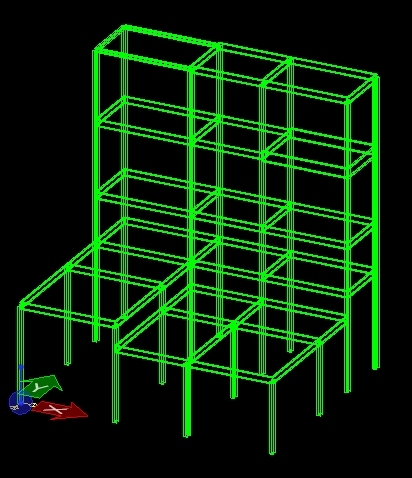
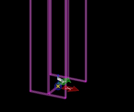
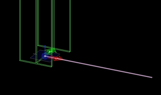
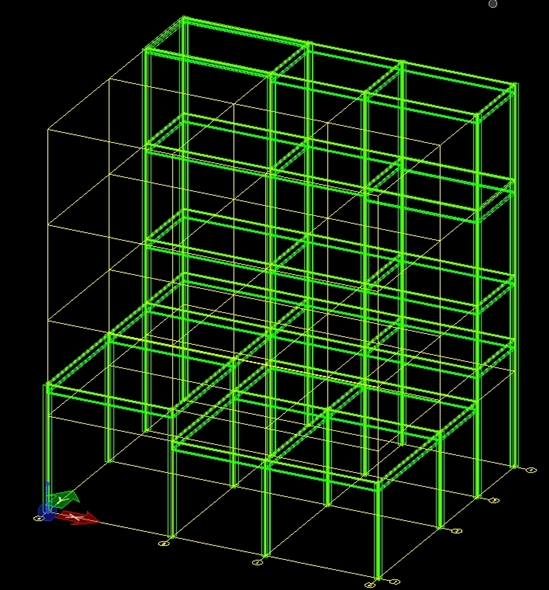
For our experiment, we used a dataset related with a building, composed of panoramic photos captured along a path inside the building, a point cloud captured of the interior, another (simulated) point cloud representing the structure inside the walls, a detailed 3D CAD model, and some metadata related with elements of the model.  We then aligned all those datasets.  This way, by switching from one dataset to the other, the user would not feel disoriented.  Our goal was to create a virtual environment in which the user could navigate and look at the data from various positions and in various combinations.  Our hope was this would provide ways of exploring the data in a new way, and perhaps open new perspectives for data visualization and intelligibility. 

We used the Occulus Rift for visualization, and the Razer Hydra as a 3D interaction device with the virtual world.  The result is a VR experience, which of course cannot be rendered here.  Unfortunately, the best alternative is to show you a video.  It is nothing compared with wearing the HMD, but you still shall be in a position to get an idea of what would be possible.

(Please visit the site to view this media)

The first part of the video shows engineering data visualization using a natural interface: panoramic images, point cloud, and 3D model.  The second part of the video shows combination of data: showing pipe elements hidden behind walls, or seen through point cloud, or seeing the laser scan acquired during construction through the model walls, or even engineering data related with elements - possibilities are numerous.  By displaying the data in the context of other data, users can see potential relationships, such as the actual location of a stud (scanned during construction) with respect to a window frame, or engineering data related with an actual ventilation duct that the user sees in the panoramic photo, etc. 

In conclusion, this is positive.  The system works, navigation is easy, and much more natural than using standard computer input (keyboard and mouse), which makes the system fun to use.  Querying objects by clicking on them on a photo is much easier than finding an entry in a database through text searching.  Data alignment and combined visualization enabled us to see correspondences that could not be seen otherwise. 

Of course, this was just a preliminary study, aimed at verifying the potential of such an application.  We could easily enhance the system by letting it query databases or display live data upon clicking on an object, let the user make measurements, display pipe content and flow direction, or spec sheets, basically any source of data related with the asset. Note that the system is VR, so it can be used anywhere for viewing the data, for instance for training, work planning, or just data exploration.  But it could also be used on site, at the location where the data was captured!  Displayed on a tablet for instance, one could display the portion of the point cloud that corresponds with what he sees in reality, and query physical objects by clicking on their point cloud representation on the tablet screen.  This would be similar to Augmented Reality, but would not require fast and accurate tracking algorithms as is normally required to overlay models with the physical world.

We are intrigued by the idea that people assemble many types of spatial information together, and then use that space as a space for action. When we provide techniques within spatial information for people to say to each other, "look at this, and (please) do this.... and here’s what I saw, and this is what I did…" then spatial information becomes a place for action, where people think and communicate, through focus, clarity, instruction, direction, affirmation, and so on.


The Occulus Rift was developed with games in mind.  It interesting to note that the gaming industry, towards which a lot of VR work has found application, may actually save the world of VR from sinking further and get more interest again.  Future will tell.  For sure, this is only the beginning of a new era in engineering data visualization and exploration.

Live mobile panoramic high accuracy augmented reality for engineering and construction

$
0
0

Those of you who have read my previous blog posts on Augmented Reality (AR) (Ref1, Ref2, Ref3) know that one of the main challenges of AR is being able to track the user’s position and orientation in real time.  Overlaying a 3D model approximately at the right location on top of the physical world can be done relatively easily – a GPS and a compass can provide sufficient accuracy for rough alignment, which is enough for several types of applications, including finding the nearest restaurant, the whereabouts of your friends, or displaying nutritional info of a product one holds in his hand at the grocery.  That is easy.

The real difficulty arises when one wants to get accurate augmentation – I mean the type of augmentation that engineers would require.  Let’s say, for instance, that an electrical engineer uses a smartphone AR app to aim at an electric cable with the phone and “click” on it with a crosshair to display – say – the live voltage being measured on that cable.  It such a situation, it is extremely important that the AR system should display the voltage related with that specific cable, and not the other one located 5 cm to the right, because the engineer’s life may depend on it…  Talking with several of our users, we came to realize that accuracy is paramount if we want to develop AR apps for engineers.  Actually, a non-accurate AR app would indeed be “cool” (for a while) but quickly abandoned by serious users, as soon as they would realize they could not rely on it.

In our previous work, we “walked around” the user tracking problem by doing the augmentation on panoramic images.  An image being static, no tracking is required, and the augmentation is very precise (no jittering is observed).  That enabled us to develop prototypes for testing hypotheses that could not easily been tested with standard AR technology (that require real time tracking).  Having said that, augmenting images is far from ideal: an image is, by definition, out of date from the moment it is captured, it may not be up to date with the surrounding world and, most importantly, it is static, so it cannot display any live event taking place in the scene (such as a user trying to interact with the augmentation).  That is rather limiting.  Live augmentation is something most researchers in the field are trying to achieve.  After all, reality is about the present – so augmenting it should be taking place now

We looked again at the reasons why we chose panoramas in the first place.  First, a panorama represents an environment – if we are to augment reality using a static image, better be one that has a very wide field of view, to show enough of the environment and this way partly compensate the fact that the camera cannot be moved.  Also an image is static, so no tracking is required, as discussed above, making the augmentation very precise.  But there was also another reason: a panorama provides image data all around the camera.  That is important, as that image data is used to calculate the camera position.  Building corners, windows, and other features are used to calculate the camera position.  But think of typical standard cameras, with their relatively narrow field of view – if your camera gets too close to a wall for instance, all the camera can see will be a featureless wall surface, and no striking feature to calculate the position from.  In such a situation, a panoramic camera has much more chance of seeing other features, decreasing the risk of falling into a situation where the camera position cannot be calculated.  That means more accurate augmentations.  In summary, panoramas are good, but they would be even better if they would not be static…

So we proposed a combination of the two: augmenting live panoramic video.  We used a nice panoramic video camera from Point Grey Research as the basis of our system, which is used as follows: the camera is installed on a tripod, at a stationary position.  In an “initialization” phase, the live panoramic stream is first aligned with the 3D model – this way the augmentation can be displayed at the right location on the panoramic stream.   This initialization process actually calculates the camera position in the model.  From that point, augmentation can take place, and a user can augment any area surrounding the camera, assuming it is visible from the camera position.  Since the camera is stationary, the augmentation is jitter free, and potentially much more accurate than with systems that require live camera tracking.  Suppose now the user wants to augment a different location in the building, he simply moves the tripod.  In the process, the system “tracks” surrounding features, calculating the camera position every frame.  When the user puts the tripod back on the ground, the system knows where the camera is located (since he tracked it while it was being moved), which means the user does not have to re-initialize the system, and can resume augmentation right away. 


Our system is composed of a panoramic camera, one tripod, and 2 laptops.  The camera produces 75 Mb of data per second, so we needed quite some processing power to augment that sort of video stream…

The system in action is shown in the following video:

(Please visit the site to view this media)

In short, this is very close to true live AR: the augmentation is done in real time, augmentation can be done from anywhere (and not from specific panorama locations), and as a bonus we get very steady (jitter-free) augmentations because the camera does not move.  But something is still missing.  In the photos below, extracted from the video demo, the user does not see the augmentation.  He actually relies on verbal instructions from his colleague, holding the laptop, to position his hand correctly with respect to the pipe / duct.  That is not ideal.

So we thought of adding a tablet to our setup:


In addition of being displayed on the laptop, the augmentation is also broadcast to a tablet, held by the user.  So the user sees what the panoramic camera system is augmenting.  The tablet is portable, so the user can walk around, and see what is being augmented.  But he sees the augmentation from the camera position.  That seems a bit strange, but look at the second video, below…

(Please visit the site to view this media)

As you could see, the system we have proposed is different from the typical AR app, in which the user user augment what is directly in front of the tablet’s camera.  In our system, the user sees what another camera sees – which means he may see himself in the augmentation.  Consequently, he may use that video as a feedback to position his hand correctly and this way interact with the augmentation.  But that system has a major advantage over typical AR systems: since the camera is stationary, the user gets no jitter on the augmentation, regardless of how much he moves with the tablet.  That could prove to be quite an advantage for engineers who require high augmentation accuracy...

Our results lead us to conclude that panoramic video augmentation is not only possible but also has many advantages over typical AR apps, such as accurate and garanteed jitter-free augmentation.  Using the system, we realized that it is probably more aligned with the needs of engineers, architects, operators, and other professionals who need to design, build, maintain and operate infrastructure. 

I agree, our setup is a bit complex – 2 laptops, a fancy panoramic camera, a tablet...  Of course, this is research.  However, we are working with devices that will, in the future, become widely available in a smaller and cheaper form.  Laptops will be more powerful, and small and portable panoramic cameras are now appearing on the market.  Our study shows the possibility is real.

Through the various augmented reality projects we have done, we realized the enormous potential of that technology in the infrastructure world.  There is an enormous amount of data available for infrastructure, and AR represents a solution for making use of that data more easily, on site, where we need it most.  Future will tell when AR will end up being sufficiently developed for being used by professionals.  But we are convinced that future it not very far...

As always, stay tuned!

Path Ways to STAAD.pro for Analysis and Design on Plant Projects

$
0
0


Path Ways to STAAD.pro for Analysis and Design on Plant Projects


If you are an avid STAAD.pro user as I am, or you
have invested many hours learning to efficiently use this structural analysis
and design software, then why invest additional time and painstaking effort
learning and using another program that barely suits your design needs? In a
few cases this may be an unavoidable reality based on project constraints and
requirements of the project managers.

However, I have good news for you!  :)

In many cases (we will discuss some in detail)
issues hindering use of STAAD.pro on specific projects can be addressed thru
software interoperability and project workflow integration. Well, what do I
mean by project workflow integration? For some of us Engineers and Designers,
we have most often received input data and produced our deliverables in
particular formats. For the Structural Engineer these file formats consist of
STAAD files (.std) along with Excel spreadsheets (.xls) and .PDF calculation
documents. For a Structural Designer these files may be 2D drawing files
(.dgn), 11x17 submittal drawings (.PDF), and 3D BIM model (.dgn).

So the question remains, what is meant by software interoperability and project
workflow integration?
Software interoperability is the
ability to use data produced in one software package, in a different software
package accurately without manually exchanging the data into a new format. Project
workflow integration is capitalizing on software interoperability to improve
project efficiency, increase accuracy, and reduce cost. Therefore not only can
you use STAAD.Pro as your structural design and analysis program of choice, you
have the added benefit of improved efficiency, increased accuracy, and reduced cost.


If project workflow integration makes so much more sense, why isn’t everyone
taking advantage of it?
There are several answers to that question.
However, my goal is to address a very important one, which is basic awareness of integration options.
Bentley Systems has been at the forefront of integration efforts for many
years. These efforts have resulted in excellent software interoperability and project
workflow integration across Bentley structural, civil, and mechanical
applications to name a few. For structural integration Bentley’s Structural Synchronizer has become the focal
point for Integrated Structural Modeling (ISM)
. For example, if you are
using STAAD.Pro for interoperability between structural modeling, structural
analysis, mechanical modeling and mechanical analysis products, bi-directional
data transfer can be accomplished with great accuracy and efficiency across the
various applications.

Many companies have recognized the opportunity to
integrate using Bentley software programs effectively and have leveraged these
capabilities to give themselves a leading edge in their market place.
What if clients, sub-contractors and stakeholders on various projects require deliverables in formats of 3rd
party vendors (Non-Bentley products)?
Are we consequently forced to use different
structural engineering software other than STAAD.pro to accomplish software
interoperability? The answer is likely No, we are not! We can use STAAD and
have our integration too.


In addition to the Bi-directional interoperability
using Bentley ISM format, there are two other formats widely used for data
exchange on engineering projects. These formats are CIS/2 (.STP) files and IFC
(.IFC) files and they can be used in instances where the ISM format is not an
available option.

So let’s look at some real world project scenarios to see how these project workflow integrations can be implemented.
We will focus on Plant Engineering and Design Projects for the examples of Path
Ways to STAAD.pro for Structural Analysis and Design. Starting within the Plant
Modeling software, we will discuss options for bi-directional data exchange to
the Structural Modeling software and then finally into STAAD.Pro. Note: Many
Plant Modeling software applications are capable of generating a CIS/2 file
that can be directly imported into STAAD.Pro. Once in STAAD.pro, we then have
bi-directional data exchange with our Structural modeling and documentation
software. In reality there are several available alternatives for project
workflow integration, therefore you can integrate in a way that best meets the
needs of your project schedule and optimizes project integration.


Thanks

Karimu.Rashad@Bentley.com

Offline spatial panoramic video augmentation

$
0
0

The term “Augmented Reality” is interpreted in various ways.  But the concept of “live” augmented reality usually means that the physical world is augmented from your current location, at the moment you are viewing the world – that means here and now.  That is what most of us have heard of – you take your smart phone, aim at something, its image is displayed on screen, and the augmentation is overlaid.  That is very cool.

But regardless of how nice and useful such a technology could be in the engineering world, it is not always something to be wished for.  For instance, live augmented reality requires the user to be on site for augmentation – that can be inefficient if the site to be augmented is far away, or if it is a dangerous place like inside a nuclear reactor.  Since live augmentation has to be done now, it precludes the review of “past” augmentations (which could be useful for documenting a site visit).  Live augmentation accuracy is also limited by the user’s movements – who has to be tracked in real time, which is hard to do accurately.  Finally, live augmentation may not always be compatible with authored communications within environments, which can be used to guide, clarify, instruct, and affirm specifically what people should see, and do.  In live augmentation, the environment cannot be guaranteed (as we never know where the user will be augmenting from).  So we thought we needed something more – an augmentation solution that would provide an answer to those problems.

Instead of augmenting live, we have proposed augmenting the world on pre-recorded media.  To provide realistic augmentations, we chose a media that is as realistic as possible: panoramic images, captured along a path.  We visited a building, used a panoramic video camera to capture video along a path inside and outside that building, and aligned the 3D model of that building with each frame of the video.  Consequently, the augmentation is no longer constrained by specific locations (as in Ref1, Ref2) but could be done anywhere along the path where the camera was moved.  The panoramic video, 3D model and path location were stored in a distributable “pre-recorded augmentation package”.  Since no tracking is required, the resulting augmentation is stable, repeatable, and authorable (actionable clarifying instructions can be authored within it), and uses only a small amount of CPU power.

We implemented our system, and tested it in the Paddy Wagon Irish Pub in Richmond, Kentucky, using a Ladybug panoramic camera installed on a tripod and dolly, and aligned each captured video frame with a detailed 3D model of the building.  The package viewer offers a view split in 2 parts: the top part shows the augmented scene, the bottom part shows the 3D map, the camera path(s) (white line) and current camera position and orientation.  The result is shown in the following video:

(Please visit the site to view this media)

Augmentation of pre-recorded media will never replace live augmentation.  Such pre-recorded packages can offer no live augmentation, and any recorded environment is, by definition, out of date.  So both types of augmentation are different, but they also are complementary: augmenting pre-recorded media offers jitter free augmentation (since no camera tracking is required), it is 100% deterministic, and it offers some navigation freedom in spite of the fact that it runs on a pre-recorded environment.  The resulting augmentation package is compatible with authorship, offsite augmentation, and with reviewing past augmentations.  The system could be used in operations (for identifying locations of hidden assets), renovations (locating structure), design (showing a model in its physical world context), and in general as a nice way of accessing information related with a building (the interface being the physical world itself).  And although the system can be used away from the augmented area, it could also be used on site, in a similar fashion to typical live augmented reality apps, but this time offering jitter free augmentation. 

Exploring the world of AR, and talking with users in the field, we realize the best solution for them is not always what we would expect.  Technology and market are taking us somewhere, but that is not necessarily always compatible with the needs of infrastructure professionals: accuracy, authorship, reliability – those have to be taken into account in application design.  Our goal is to make sure the AR tools we develop for them are not just toys, that they become useful and  totally reliable.  So far our results show we are making some progress in that direction…

Want to read more?  Check our paper:

Côté S., Barnard J., Snyder R., Gervais R., 2013.  Offline  spatial  panoramic  video  augmentation  for  visual communication in the aec industry.  Proceedings of the 13th International Conference on Construction Applications of Virtual Reality, London, November 2013.  PDF

Many thanks to Chuck Fields, owner of the Paddy Wagon Irish Pub in Richmond, Kentucky, for giving us access to his building and permission to share our results!

"Flache" DWGs aus Zeichnungen mit dynamischen Ansichten

$
0
0

Folgende Vorgehensweise zur Erstellung "flacher" DWGs aus Zeichnungen mit komplexen dynamischen Ansichten ist resourcenschonend und führt über das manuelle Merge der sichtbaren Kanten in Kopien der Plan (Drawing) Modelle. Zuletzt wird das DWG Modell abgespeichert.

  1. Ausschnittvolumen im 3D Modelldefinieren
  2. Festansichten (Schnitte) davon auf Plan Modelle(Drawing) (Hier kann der Cache für Visible Edges angeschaltet werden – dauert hier ca. 20 Minuten bei mir. Kann ggf auch als Batch laufen)
  3. Plan Modelle skaliert auf Zeichnungsblatt (Sheet) platzieren.
  4. Kopie der Datei erstellen (DGN ohne Merge)
  5. Merge into Master in den einzelnen Drawing Modellen (kann als Batch laufen – lohnt aber erst bei einer Anzahl von Dateien – ca. 20  Minuten bei mir – gecached sehr schnell)
  6. Für DWG braucht es zusätzlich ein „leeres Design-Modell“ - erstellen (kann schon bei Schritt 2 passieren)
  7. Save As … DWG mit Merge (das geht jetzt sehr schnell da nur noch 2D Elemente zusammenzuführen sind)
  8. Utilities>Design >File Cleanup (Duplicates usw.)
  9. Compress…

Announcement: ProStructures V8i Ss6 Software (MicroStation & AutoCAD) & Plug-in/ObjectEnabler released

$
0
0

ProStructures V8i SELECTseries 6 has been released for both platforms, MicroStation & AutoCAD. The release of the plug-in (MicroStation) & ObjectEnabler (AutoCAD) has also been done.

Note: This new release of ProStructures is also the release where licensing for the software was changed. There is only one license level for both ProSteel & ProConcrete compared to previous versions which had different levels of licensing.


You can find the software installers by searching for ProStructures in the "Support > Downloads and Updates > Software Downloads" using the "SELECT Released Products" filter.


If looking for the Plug-in for MicroStation or the ObjectEnabler for AutoCAD simply change the filter to "Free Update/Utilities"


Note: These two tools (Plug-in & ObjectEnabler), should ONLY be installed on machines that DO NOT have ProStructures installed on. If you are using a machine with ProStructures installed on it, these tools are NOT needed.


AECOsim Building Designer - Añadir nuevas columnas al Catalogo

$
0
0

A continuación se describen los pasos a seguir para añadir nuevas columnas al catálogo de columnas disponibles con AECOsim Building Designer.

1.       Seleccionar la función necesaria para poner el tipo de elemento que necesitamos. Por ejemplo “Place Steel  Column”

2.       Seleccionar un elemento activo (por ejemplo, uno generico, como “Column” y hacer clic en “Save Copy of Catalog Item” para crear una copia de este elemento.

3.       Definir el nombre del nuevo elemento que vamos a crear, por ejemplo “Pilar HEB180”

4.       Ahora que tenemos creado el nuevo elemento, definimos la sección estructural por defecto que le vamos a asignar haciendo clic en la opción “Select Section”

5.       En el dialogo de selección de Sección Estructural, hay dos campos para hacer un filtro y encontrar la sección correcta: Code y Type, o también se puede escribir en el campo sección las primeras letras de la sección que estamos buscando para que haga un filtro


6.       Si la sección que estamos buscando no está entre las disponibles, entonces necesitaremos cargar algún fichero adicional. Para eso, hacemos clic en el menú File à Open…

7.       Seleccionamos la carpeta “Data” dentro del dataset que estamos utilizando:

 8.       Dentro de la carpeta “Data” encontramos todos los estándares disponibles con AECOsim. Seleccionamos el que necesitamos, por ejemplo “Spanish.xml” y pulsamos sobre “Add

9.       El fichero de sección seleccionado aparecerá en la lista de abajo, y podemos pulsar “Done” para salir de este diálogo.

 10.   El estándar que hemos cargado aparecerá en la sección Code. Si alguna sección aparece definida en varios estándares solo se cargara una vez. Pulsamos OK para volver al dialogo “Place Steel Column” que habíamos seleccionado al principio.

11.   Ahora que nuestro nuevo elemento de catálogo tiene definido correctamente el valor de sección por defecto, solo debemos guardar el elemento con la definición actual pulsando en “Save Catalog Item”

Incluyo en el post un fichero pdf con los mismos pasos descritos aqui.

Tip No.10: Installing and using the ProSteelTools add-on (AutoCAD version only)

$
0
0

This add-on tool is only available for the AutoCAD version of ProSteel for now.

Hopefully next year we will have them also available for the MicroStation version.


1) Installation


First you need to download the zip file that contains the tools. It is located here:

For SELECTseries 6 :  ProSteelTools SelectSeries 6 for Autocad Version 12.11.2013
For SELECTseries 5:   ProSteelTools SelectSeries 5 for Autocad Version 21.02.2013

Once downloaded, extract the files in a temp folder and run SETUP.EXE

This should now allow you to load the Tools into your ProStructures version running ontop of AutoCAD.

Open ProStructures and type MENULOAD at the command prompt.

Using the Browse button, go to the "Menus" folder located under the language pack you are using under the localized folder of the ProStructures installation folders.


Select ProSteelTools_S6.cuix (if using SELECTseries 5 file ends in "_S5".cuix) file and press "Open"

Now press "Load" in order to have the toolbars available. From all the toolbars, the main one is:

All the others are fly-outs from it.


2) Usage


The ProSteelTools is a collection tools that give you extra controls over the ProSteel elements. They are the following:

  • Show all - unhides all objects
  • Weight - calculates the weight of all selected objects
  • Group Display Tool - displays groups based on Positionnumber
  • Update Group Name Plates - Updates the group name after changing plates as main parts
  • Swap Main Part - using another part as main part without recreating the group
  • Layout Tool - changing display options for all selected objects
  • Modification Tool - searching, deleting and replacing modifications
  • Object Based Search - Search tool based on properties of a selected object
  • Filter Mirrored Objects - Filter for mirrored objects
  • Color From Layer - reassigns color based on layer color
  • Color From Part Family - reassigns colors based on part familiy colors
  • Export SAT - Export feature for complete model or groups or single parts
  • Dialog Standard Positions - resets the position of dialogs to default

You can see videos explaining the usage of these tools in these short videos created by our colleague Steffen Knoll.


Video Part 1 features:

  • Show all - unhides all objects
  • Weight - calculates the weight of all selected objects
  • Group Display Tool - displays groups based on Positionnumber
  • Update Group Name Plates - Updates the group name after changing plates as main parts
  • Swap Main Part - using another part as main part without recreating the group

(Please visit the site to view this media)


Video Part 2 features:

  • Layout Tool - changing display options for all selected objects
  • Modification Tool - searching, deleting and replacing modifications
  • Object Based Search - Search tool based on properties of a selected object
  • Filter Mirrored Objects - Filter for mirrored objects

(Please visit the site to view this media)


Video Part 3 features:

  • Color From Layer - reassigns color based on layer color
  • Color From Part Family - reassigns colors based on part familiy colors
  • Export SAT - Export feature for complete model or groups or single parts
  • Dialog Standard Positions - resets the position of dialogs to default

(Please visit the site to view this media)


Did You Know? RAM Connection Gussets and Base Plates

$
0
0

Did You Know… RAM Connection has an extensive library of connection types built into the program? I frequently am asked, "Can RAM Connection do [     ]?" where the blank is filled in by a specific connection type.

I previously wrote a couple of blogs discussing shear and moment connection types.  There are two additional connection types available in RAM Connection: gussets and base plates.  These connection types are equally important, and normally more difficult to design.  You may download a quick reference PDF of these connection types at the bottom of this blog post.

All gusset and base plate connections in RAM Connection are designated as “smart.”  If I lived in Boston I’d even call them “wicked smaht.”  A smart connection optimizes certain aspects of the connections, such as plate thickness, weld size, number of bolts, etc.  The optimized aspects vary depending on the template you assign.

So without further ado, here are the majority of the gusset and base plate connections available in RAM Connection.  This is not an exhaustive list.  RAM Connection is customizable and it would be difficult to list every single connection available.

Gusset Connections

     G1. Columns Beams Braces _ Double Angle

     G2. Columns Beams Braces _ Double Angle Continuous

     G3. Columns Beams Braces _ Single/Shear Plate

     G4. Columns Beams Braces _ Directly Welded

     G5. Chevron (Shown with Bolted Angles)

     G6. Vertical X-Brace

     G7. Columns Beams Braces _ Directly Welded _Concentric Braced Frame

     G8. Chevron_Concentric Braced Frame (Shown with Welded Tubes)

     G9. Gusset Base Plate – See Base Plate Connections


Base Plate Connections

     BP1. Pinned Base Plate

     BP2. Fixed Uniaxial Major Axis Base Plate

     BP3. Fixed Uniaxial Minor Axis Base Plate

     BP4. Fixed Uniaxial Both Axis Base Plate

     BP5. Fixed Biaxial Base Plate

     BP6. Gusset Base Plate (Shown with Welded Tube)


Announcement: ProStructures/ProConcrete's first online training

$
0
0

The first online training for ProConcrete on MicroStation will take place next week (from Sep. 17th to 18th). This training is from 8am to 5pm North American Eastern Time.

This will be delivered on the new release of ProStructures, V8i Ss6, which will be release Monday Sep. 16th on our SELECTserver.

Added note: There have been issues with the release of Ss6. It has been delayed a few days. Nevertheless the training will still take place using an internal build (Release candidate)

There is still time for you to register. Follow the link bellow and login to register.

­­>>> REGISTER HERE <<<

Other dates are available later in the year as you can notice at the bottom of the link.

Instructor changes: I will be delivering the 1st and 2nd of these trainings. My colleague Doug will be delivering the 3rd (and last one for 2013).


A Guide to RAM Concept Information on the Web

$
0
0

There is a wealth of technical resources available to our RAM Concept user base. Over the past several years our structural product experts have produced how-to video tutorials, product tours, and tech notes that address a wide range of topics and questions the RAM Concept user community commonly raises. Most, if not all, of this content resides on either our own BE Communities site or youtube. Up until now there’s been no single master list of RAM Concept product information. This post is a step in that direction. This list identifies and describes all the content we know to exist, and we'll continue adding to it and more effectively organize the items. Many thanks are in order to the contributors of this content, and in each landing site you’ll see the name of the authoring Bentley colleague. In the meantime feel free to pass along suggestions for content to me at Josh.Taylor@bentley.com.


RAM Concept Insider Skills

Part 1

http://www.youtube.com/watch?v=4NpdZrLBWLc

1)      Reconfiguring slab and load polygons by adding or removing nodes

2)      Refining and simplifying program-generated design strips (2:35)

Part 2

http://www.youtube.com/watch?v=mkSacbm0prA

1)      Interpreting errors and warnings during the analysis

2)      Reviewing the error log (2:20)

3)      Locating errors by coordinates (2:45)

4)      “Line is too short” error (3:30)

5)      Using perspective views to troubleshoot errors (5:16)

6)      Fixing the “Tendon is out of slab” error (6:01)

7)      Cross section trimming considerations (7:47)

8)      Effect of the cross section slope limit setting (13:25)

Part 3

http://www.youtube.com/watch?v=4_lKyouA1PI

1)      Reviewing slab precompression magnitudes using 2D plots

2)      Displaying slab stress plans for specific load cases (2:30)

3)      Simplifying the review of bar design results by varying display settings (3:45)

4)      Reviewing live load reduction values calculated by the program (7:18)

Part 4

http://www.youtube.com/watch?v=H2Np4_KIW5c

1)      Using the Cross Section Orientation tool to rationalize the placement of program-selected reinforcement

2)      Refining tendon layouts using the tendon void and tendon parameters commands (2:50)

3)      Analysis of floors for footfall vibration (8:00)


RAM Concept Tech Snippet: Tendon Tools

http://www.youtube.com/watch?v=Sv-LuqjVSIs

How to lay out tendons using the Generated Tendon method, a much quicker alternative to manually creating individual tendons.


RAM Concept Tech Snippet: Working with Reinforcing

http://www.youtube.com/watch?v=L2-F6-5oPe0

How to rationalize program placed reinforcement to a simplified layout.


Exporting a RAM Concept floor to RAM Structural System

http://www.youtube.com/watch?v=DU60wpCTEIY

A video demonstration of the export of a RAM Concept model into RAM Structural System for the multi-story analysis and design of the superstructure.


Designing Slabs in RAM Structural System

http://communities.bentley.com/other/old_site_member_blogs/bentley_employees/b/annmarie_garkohill_blog/archive/2013/02/15/designing-slabs-in-ram-structural-system.aspx

A quick start guide to utilizing RAM Concept as a module within RAM Structural System.


Animation of plots in RAM Concept

http://www.youtube.com/watch?v=_uLdA3lAwAI


Balance and Hyperstatic Loading

http://communities.bentley.com/products/structural/structural_analysis___design/w/structural_analysis_and_design__wiki/8068.aspx

A quick and effective explanation of balance and hyperstatic loads.


RAM Concept Capabilities and Modeling FAQ

http://communities.bentley.com/products/structural/structural_analysis___design/w/structural_analysis_and_design__wiki/2056.aspx

Some basic discussion on modeling limitations in RAM Concept.


RAM Concept Design Strips

http://communities.bentley.com/products/structural/structural_analysis___design/w/structural_analysis_and_design__wiki/4507.aspx

1)     Defining manual design strip boundaries

2)     Cross section trimming

3)     Design strips and slab openings

4)     Full width design strips versus column/middle

5)     Design strips for beams


RAM Concept Files FAQ

http://communities.bentley.com/products/structural/structural_analysis___design/w/structural_analysis_and_design__wiki/2057.aspx

Some notes on file management in RAM Concept, including mat files and CAD backgrounds.


RAM Concept Lateral Self Equilibrium Analysis

http://communities.bentley.com/products/structural/structural_analysis___design/w/structural_analysis_and_design__wiki/3086.aspx


RAM Concept Load History Calc Options

http://communities.bentley.com/products/structural/structural_analysis___design/w/structural_analysis_and_design__wiki/6191.aspx

A discussion of the settings and options in RAM Concept’s load history deflection analysis.

1)     Creep factor

2)     Shrinkage strain

3)     Shrinkage restraint

4)     Aging coefficient


RAM Concept Loading

http://communities.bentley.com/products/structural/structural_analysis___design/w/structural_analysis_and_design__wiki/3087.aspx

Information on some nuances of applying loads to the floor.


Getting More Out of Your RAM Concept Plots

http://communities.bentley.com/other/old_site_member_blogs/bentley_employees/b/annmarie_garkohill_blog/archive/2013/04/12/getting-more-out-of-your-ram-concept-plots.aspx

A review of important settings for control of plot information, color coding, and display style.


RAM Concept Plans and Perspectives

http://communities.bentley.com/products/structural/structural_analysis___design/w/structural_analysis_and_design__wiki/2058.aspx

Troubleshooting a few issues users have come across when viewing plans and perspectives.


Did you Know? RAM Concept Plans and Perspectives

http://communities.bentley.com/other/old_site_member_blogs/bentley_employees/b/beth_suminski_blog/archive/2013/06/14/did-you-know-ram-concept-plans-and-perspectives.aspx

How to customize plots in RAM Concept to show specific information according to your own preferences.


RAM Concept Reinforcing FAQ

http://communities.bentley.com/products/structural/structural_analysis___design/w/structural_analysis_and_design__wiki/8362.aspx

1)     Displaying governing code provisions

2)     Modeling of user reinforcing

3)     Suppressing additional program reinforcing during design

4)     Slab face setting for reinforcing

5)     Designing using a single reinforcing layer

6)     Customizing the bar callout style on the reinforcing layer


RAM Concept Shear Reinforcement

http://communities.bentley.com/products/structural/structural_analysis___design/w/structural_analysis_and_design__wiki/3094.aspx

Answers to commonly asked questions on shear checks and one-way shear reinforcement.


RAM Concept Structure

http://communities.bentley.com/products/structural/structural_analysis___design/w/structural_analysis_and_design__wiki/2059.aspx

Answers to a number of commonly asked questions dealing with the modeling and viewing of elements, fixities and restraint, and settings for soil in the design of mats and rafts.


RAM Concept T-Beams and Axial Forces

http://communities.bentley.com/products/structural/structural_analysis___design/w/structural_analysis_and_design__wiki/4412.aspx

An explanation of the significance of the T-beam setting for strip generation, and a quantitative illustration of how design forces are resolved when using this option.


RAM Concept Tendons

http://communities.bentley.com/products/structural/structural_analysis___design/w/structural_analysis_and_design__wiki/2060.aspx

Answers to commonly asked questions related to tendon placement, and how to resolve common warnings.


Intelligible Information Environments

blogging for multiple audiences

$
0
0

Earlier this year I started blogging also at another blog site. A smaller audience than here on Bentley Communities, but just another channel, and so far there have been readers from 64 countries.

Thank you for reading my posts!

Here is the other blog: http://dagsljus.wordpress.com/


An update to STAAD Foundation Advanced SS2 (version 6.2) is just released

$
0
0

The update (patch) of STAAD Foundation Advanced V8i SELECT series 2 (Release 6.2) is now available on SELECT to download. It is recommended for all users of STAAD Foundation Advanced version 6.2 to install this update package. This will update your existing 6.2 installation to the latest version.

To download the patch:

  1. Go to http://appsnet.bentley.com/myselectcd/ in your web browser.
  2. Select STAAD Products from the Products list.
  3. Select “All” in the Download Category list.
  4. Click Search. The list of all updates is returned.

  5. Select the appropriate patch (06.02.00.59) of STAAD Foundation Advanced V8i
  6. Click Continue and download the update installer.


Similar to previous updates, there are several enhancements and bug fixes included in this package. Here are examples of a few major enhancements.

Combined footing design moment calculation at column faces

This is an important and long pending item. Previous versions used to take maximum and minimum moment solely based on bending moment diagram and there was no check in place to ignore higher moment values underneath the column or pedestal. Now program automatically calculates moment at all column faces and ignores moment points underneath the columns. Previous approach sometimes could lead to more conservative design, so new version leads to a more realistic design.

Foundation design based on ACI 318 now supports 3 versions of the code

This feature was previously already added in “general Mode” but was missing in “Plant Mode” and “Toolkit Mode”. With this update package program will now support ACI 318-05, ACI 318-08 and ACI 318-11 for all modules of the program.

  
Enhanced spreadsheet import/export capabilities

Spreadsheet import/export is a popular feature in STAAD Foundation. This update added a few more tables to the import/export capabilities. The spreadsheet feature now supports ‘Soil Bearing Capacity Factor”, “Self weight factor” and new ACI 318 code version tables. Soil bearing capacity factor table is used to input load specific allowable bearing capacities. The best examples are load combinations involving temporary load cases such as wind and seismic. Many codes allow 33% increase of bearing capacity for wind and seismic load cases. An input of 1.33 against such load combinations in soil bearing capacity factor table will increase soil bearing capacity by 33%.


Automatic load combination generation based on ASCE 7-2010

ASCE 7-2010 table is now added as another option for automatic load combination generation. Many users requested for this tableas it is now being used as the standard load combination table replacing ASCE 7-2007 version. However, for the convenience of the users both versions of the load combination tables are supported.

New Input For Pedestal Steel % Reinforcement For US Code From Global Settings:

For the convenience of experienced users, required minimum and maximum % of steel for pedestals can now be directly specified. By default, the program will use code specified steel %. One might argue why a program would allow to modify code specified minimum/maximum steel. The answer points to the different design practices among different organizations around the world. However, those user specified % will be printed on the calculation sheet for review purposes.


This is probably the last and only update to STAAD Foundation Advanced SS2 (version 6.2). The next version of the program (version 7.0) is scheduled to be released by the end of this year which will include several exciting new features.

Tip No.8: Generating a Workframe around and existing structure

$
0
0

In this tip, I will show you how to get ProStructures to automatically recognise the steel elements (Beams & Columns) in a model in order to build the corresponding Workframe.

This could be used for example on a structure built in STAAD, imported into ProStructures using ISM to which we now want to add the Workframe.

First, be aware that any structure imported from STAAD will have all members inserted from their middle. Which means all beams will be "offset " half their height upwards. It is actually a "good" thing to have before executing this tip because the Workframe will be built at TOP of all COLUMNS & MID-LINE of all BEAMS.

Once you have the steel you want to create a Workframe around, start the workframe command and select the bottom of the front/left column (of the plan view orientation you want to create with the workframe) as the insertion point.

Then select the orientation of the X axis (bottom of plan view to be generated with this workframe)

At this point the Workframe dialog box will pop-up, showing the values used the last time you used the Workframe, which obviously do not correspond to this specific structure.

Make sure you UNSELECT the 3 check boxes at the left hand side of the Layout tab as shown below in order to activate the "manual" entry of distances.

Now expand any of the 3 pull-downs, and anywhere inside the pull-down, left click with the mouse WHILE holding down the left hand side of the keyboard CTRL key.

You should now be prompted to select the items you want to consider in order to build this new Workframe. Select the whole structure.

Notice how all lines of Workframe appeared (as mentioned in the beginning) in the middle of all beams and on top of all columns. Now we can move those beams back down to their top of steel.

Select ALL beams, and get their "PS Properties" dialog box to open. In the Position tab, notice how their insertion point is the middle. Simply select the top of steel and all beams will shift up by half their height regardless of the fact they are not all the same height.


Proyecto Hidro

$
0
0

Buenas, estoy iniciando en el aprendizaje de Hammer, ya que me lo recomendaron para el analisis de trancendentes, entonces me surgen las siguientes dudas:

1.Necesito colocar una reduccion de diametro, pero no se si el programa tendra algun item especial para esto, o si en el inicio de la tuberia con el diametro ya reducido se puede colocar algun coeficiente de perdida localizada

2.hay un punto donde mi tuberia se bifurca para ingresar con distintos caudales hacia las turbinas, existira alguna libreria con items como estos.

3. tengo elementos de desacarga que en otros paquetes como WHAMO ( del US ARMY), en el que se definen elementos Dummy, los cuales no tienen una definicion fisica, entonces quisiera saber si existe alguna forma similar de imitar el codo de aspiracion o la descarga hacia el siguiente reservorio es directamente.

Gracias de antemano por su colaboracion.

SS5 - Stretching / Altering Bay Sizes

$
0
0

With Interfering Elements

When a model is built, if for some reason the bay size needs to be altered after the miscellaneous steel has been placed, then altering the model may become a bit more difficult. The reason for this being that not all miscellaneous steel will react the way the user is expecting. One example of this would be bracing elements created using the commonly used dynamic bracing command. In this example bracing elements are parametric objects that are tied to the line or points originally selected when placing the elements.

Even though the parametrics of the object will allow for certain automatic updating functions to take place, radical changes like bay sizes may require that the parametric objects in question be replaced.

Using the bracing example mentioned above, the easiest method of doing this is to create a template from the parametric dialog window, remove the original elements and place them again using template to automatically setup the elements to their original state.


Cut lines or post modifications will also need to be repeated in this case.

Without Interfering Elements

If you do not have any interfering elements then a simple stretch command can be used to enlarge a bay area.  This will stretch the members in the selected area, along their current path to any length required. It should be noted however that if a workframe was used, then this will need to be modified afterwards from the workframe dialog window to match to new model sizes.

In a situation like this, stretching the elements along their existing path will simply enlarge the bay area without any adverse effects.

Three things should be kept in mind however when using this method.

  1. All items should be showing. Anything hidden or not showing for whatever reason will not be stretched.  Turn on layers that contain elements, ‘regen’ items that are hidden, display and area class objects should all be showing and clipping planes turned off. The use of any or all of these functions will cause the hidden objects to not be affected by the stretch.
  2. All objects will be stretched along their current path. If horizontal members are being stretched then this method should work fine but keep in mind that if something is angled that the members will not follow the horizontal shift but rather will continue to extend along their current course to the new point selected by the stretch command.
  3. The workframe itself should not be selected. The reason for this being that the workframe lines will be moved from its original location and not stretched. For this reason when selecting the elements to stretch, deselect the workframe lines before actually stretching the members themselves.


NOTE: The upcoming MicroStation version of SS6 may include code that allows the MicroStation stretch tool to better handle the stretching functions of ProStructures elements.


Tip No.9: Using the ProStructure Snaps on Ss6 (MicroStation release only)

$
0
0

This tip only applies to the MicroStation version of ProStructures SELECTseries 6 (not release yet)

With ProStructures SELECTseries 6 for MicroStation, you will notice a new page available in the Global Settings called "Snaps".

In this page you have the option to enable what is called the "ProStructure snaps" or the "ProStructure legacy snaps" and to enable the "ProStructure tooltip" as well.

What happens if I don't activate any of the two snaps? What is the difference between the two snaps? What is the tooltip for? I'll explain this in this tip.


Q.1) What if I don't use neither of the snaps?

A.1) In this case you will be using the standard MicroStation snaps. The Tooltip option, even if enbled will not display.


Q.2) What do the ProStructures snaps do?

A.2) When activated the selection of insertion points will forget the MicroStation snaps and use the shape's start point, end points and mid point to distribute.

You can change these to the MicroStation "Keypoint Snap Divisor" by pressing the "K" key and selecting the number of division you want. For example 6 in the image bellow.

You will also get the option to flip from all 10 available snaps points at each division point allong the shape using the keyboard Arrows, PageUp, PageDown, Home & End keys.

The keys do the following:

  • Arrow keys = "up/down" (1-4-7 if starting at point 1) or "left/right" (1-2-3 if starting at point 1)
  • Page Up/Page Down = cycles between ALL points sequentially
  • Home = goes to the insertion point
  • End = goes to the center of gravity (point 10 in the image above if the element is an angle)


Q.3) What do the ProStructures legacy snaps do?

A.3) When using only legacy snaps, you will get standard MicroStation snaps and centerline snaps at both ends and divisions (MicroStation "Keypoint Snap Divisor" once again) of the shape.


Q.4) What is the tooltip and how do I customize it?

A.4) When activated the tool tip will show while selecting insertion points. The information shown by default is the following:

This infornation can be customized by editing the tooltip.ini file located in the PRG folder.

Lets say we want to change the tooltip to show the name, length, material & description index.

This is the original line we would need to change:

Form=Postion=%POSITION%\nPickPoint=%PICKPOINT%\nType=%TYPE%\nShapeName=%NAME%\nZcoordinate=%ZCOORDINATE%

This is the new line to use:

Form=Name=%NAME%\nLength=%LENGTH%\nMaterial=%MATERIALNAME%\nFDF=%FREEDESCRIPTION%

 Note: In order to get a better result with these snaps it is suggested to be in wireframe mode.


Viewing all 289 articles
Browse latest View live


<script src="https://jsc.adskeeper.com/r/s/rssing.com.1596347.js" async> </script>